This thread has been locked.

If you have a related question, please click the "Ask a related question" button in the top right corner. The newly created question will be automatically linked to this question.

MCP6072 Equivalent

Other Parts Discussed in Thread: OPA387, OPA2387

Hello,

I am currently working on a circuit that can read the solar reference cell voltage output value. I am using  MCP6072 for amplify to STM32F0 microcontroller ADC. I want to change it. Can you suggest me up to date TI op-amp which is low noise, high precision.

Best Regards,

Metin Enes YILDIRIM

  • Hi Metin, 

    From the cross reference search, MCP6072 is equivalent to LMV932MA op amp, but these are general purpose op amp. 

    If you are looking for precision, low noise, low drift op amp for the application, I would recommend OPA388 or OPA387 or other zero drift low voltage op amps. We have wide selections of precision zero drift op amps that are well suited for the application. 

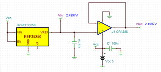
    Below is a simulated example. We also have many high precision, low drift bandgap references at different price points. 

    https://www.ti.com/power-management/voltage-reference/products.html?keyMatch=PRECISION%20VOLTAGE%20REFERENCE

    OPA388-Q1 Buffer.TSC

    If you have other questions, please let us know. 

    Best,

    Raymond

  • Hi Raymond,

    Thanks for your recommends. I am going to use a current sensing circuit for reference cell output measurement. the shunt resistor value is 100 mohm and my shunt resistor Voltage between 500 uV - 60 mV. I am going to amplify to STM32F0 ADC input range which is 100 mV to 3.2 V.

    So my question is in OPA387 aplication circuit there is bidirectional current sense circuit but I don't have negative values. Can I use this op-amp current sense circuit with out Vref part. If I can, do I need to remove R1 and R2 resistors and calculations still work?

  • Hi Metin, 

    Can I use this op-amp current sense circuit with out Vref part. If I can, do I need to remove R1 and R2 resistors and calculations still work?

    R1 and R2 resistors have to be there for the difference amplifier to work. 

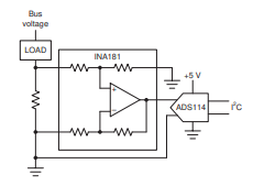
    I think that you are thinking about TI's current sense monitor product, where the current monitor is used for bidirectional current sensing. 

    https://www.ti.com/amplifier-circuit/current-sense/analog-output/products.html#2192=Ultra%20precise&

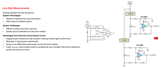
    There are minimum 2 ways to implement these. One is using a precision op amp as prescribed in Figure 8-1 (discrete design approach). The other method is using the current monitor, which is an integrated current sensing approach that typically comes with a fixed gain. The current sensing front end may use instrumentation amplifier, difference amplifier or other shunt measurement techniques to extract the current information. Please see the application note below, which is likely what you have in mind per your inquiry. 

    https://www.ti.com/lit/eb/slyy154b/slyy154b.pdf?ts=1702975541645

    Please let me know which approach you are interested in. We can support the discrete current sensing approach as shown in Figure 8-1. If you want to use current monitor for your application, you have to contact the current sense monitor support team for the recommendation. 

    Best,

    Raymond

  • Hi Raymond,

    Thanks for your reply again. I want to use this circuit below with OPA2387. I am going to connect output of the circuit to STM32F0's ADC pin. Is it okey for using?

  • Hi Metin, 

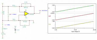
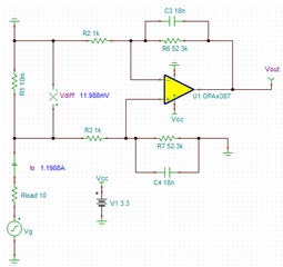
    Ok, you want to implement discrete current sensing approach. The best option is configuring the input stage with a difference amplifier, which it will reject the common mode noises better than the signal ended input circuit. 

    Since I do not have the design requirements, please consider the simulation below is an example. 

    OPA387 difference amplifier 12222023.TSC

    If you have other questions, please let me know. 

    Best,

    Raymond

  • Hi Raymond,

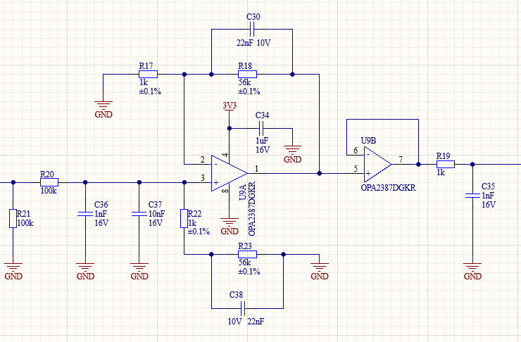
    Thank you again for your help. I updated my schematic as you suggested as follows. I couldn't find an 18nF capacitor so I used 22nF. Do you think my filter circuits are correct? Do I need to check them too, will my 100k ohm R20 resistor cause a problem?
    And finally, a few parts about the gain stuck in my mind. For the non inverting op-amp circuit I designed:
    Gain= 1 + R18/R17
    or not. Because in your simulation, the +1 part of the gain does not come, is this related to the fact that it is differential. By the way, I also made my gain value 57.

    Best Regards,

    Metin

  • Hi Metin, 

    The revised schematic is not what I proposed, and it is incorrect. My understanding is that you are sensing current in the application. 

    If the application is sensing current with shunt resistor of 10mΩ or 100mΩ, the following circuit is what I recommend. This is a difference amplifier, and it is NOT non-inverting op amp configuration. 

    The discrete form is the following, low side current sensing. You can change the gain from 52.3kohm to 56kohm, and 18nf to 22nf. 

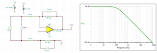
    The difference amplifier's AC response is shown below, and you may not need extra RC filter circuits. 

    OPA387 difference amplifier AC response 12232023.TSC

    Please simulate these, since I posted all these files. 

    Best,

    Raymond