This thread has been locked.

If you have a related question, please click the "Ask a related question" button in the top right corner. The newly created question will be automatically linked to this question.

INA181: Output Impedance of INA181

Expert 1155 points
Part Number: INA181
Other Parts Discussed in Thread: INA185, DRV8305

Hello,

I want to analyze INA181 as a TMS320 ADC driver, according to SPRACT6A.

At some step I need to know the GBP of INA and output series resistance.

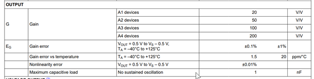
For A1 INA we have in datasheet only Bandwidth at 20x Gain, it is 350. Can I calculate GPB then as 350x20 = 7MHZ? Is this correct?

TI's Analog Engineer Calculator calculates required GBP to be 48MHz (at 12bit, 3.3V, 75n Acq Time, 15pF Csh) - what I am loosing if I use INA181A1 with 7MHz only? The accuracy, right?

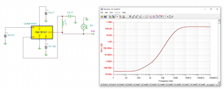
Also I want to know the series output resistance, for that i tried making the simulation in TINA but the result looks strange (attached picture and simulation file)? Can you advice me if my simulation is ok if i want to get the output series resistance?

And can I skip series resistor to TMS320 ADC while having 300pF input capacitor? What kind of simulation I need to do to check if without resistor it would be stable? Is there any instruction for TINA?

Regards,

Adam  INA_output_impedance.TSC

  • Hello Adam,

    I agree. The INA181 model Zout has a decent inductive portion, but it starts and settles at inaccurate values. We are working on updating this behavior.

    The easiest thing to do it to just use the INA185A1 spice model. The INA185 has the same Zout curve as the INA181 and the INA185 model correctly models the Zout. I have included a simulation showing this and an another way of simulating Zout in spice.

    I have also attached a simulation model to get you started on simulating how the INA181A1 would drive a switching ADC. It is not completely filled in with specific ADC input impedance values and with the chosen conversion time, but it is straight forward to finish.

    Here is a helpful application note on how to perform this type of analysis.

    https://www.ti.com/lit/an/sboa443/sboa443.pdf

    Sincerely,

    Peter

    INA185+SAR.TSC

    INA185_Zout.TSC

  • Thank you very much. This is all what I need :)

    Could you also advice if I want to use DRV8305 build in Current Sense Amplifiers, how can I simulate the amplifiers itself? Is there any stand-alone amplifier that have similar parameters to DRV8305 Amplifiers so that I can use that part for reference in simulation?

  • As I am not sure what is the series output resistance of DRV8305 Amplifiers, there is one diagram shoiwng it's 100 Ohm, but I am not sure.

  • Hey Adam,

    There does not seem to be a stand alone model for this.

    One quick option is to just use a generic and/or adjustable spice op amp model and set the open-loop gain (Aol) and dominant and/or second poles such that gain cross 0 db (unity) at 2 MHz. Other parameters like input offset and input bias current are more straightforward to adjust according to datasheet specifications.

    For more information I have included one of our experts for this device on this forum. Although I would recommend starting a new post as well.

    Sincerely,

    Peter

  • Thanks again.

    Ok, I will raise new post regarding DRV.

    One last question regarding INA181.. could it be potentially unstable with 150pF load? 

    I will try to simulate it and get the answer, but maybe for you it's obvious that 150pF way to low and for sure will not cause stability issues.

  • Helllo Adam,

    This should be fine with 150pF.  See datassheet.it states 1nF.