Other Parts Discussed in Thread: LP2985
Dear Expert
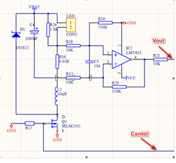
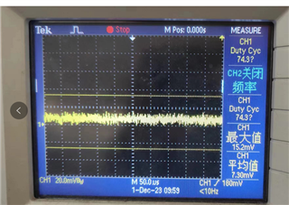
① Test method: The oscilloscope uses Tektronix's TDS2024C. After the operational amplifier is powered on (the operational amplifier is powered by LDO output 3.0V, model LP2985), keep the operational amplifier in its initial state as shown in the schematic diagram without applying an input signal. The oscilloscope probe is grounded together with the operational amplifier, and the probe is tested at the output end of the operational amplifier to measure its ripple;
② The oscilloscope is set with a bandwidth limit of 20MHz, AC coupling, and a probe size of 10x;
③ Probe parameters: Model: Tektronix TPP0201200MHz, 10M Ω/<12pF, 10X.
The schematic diagram is as follows. Among them, VBAT=4V, VCC=3V, and LED is the light-emitting diode load.
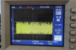
Test environment: Based on our application circuit, according to the conditions shown in the diagram (magnified by 51 times), after powering on the operational amplifier and without applying any signal at the input end, under the same premise, the abnormal IC output ripple is close to 3V, while the normal IC ripple is 20mV.


