This thread has been locked.

If you have a related question, please click the "Ask a related question" button in the top right corner. The newly created question will be automatically linked to this question.

OPA549: Getting more current than I I intended to provide

Part Number: OPA549

Hello, 

I am building a battery charger and discharger, and I am using a OPA549 chip to supply current to the battery to charge and discharge the battery. Below is the schematic I am using currently. 
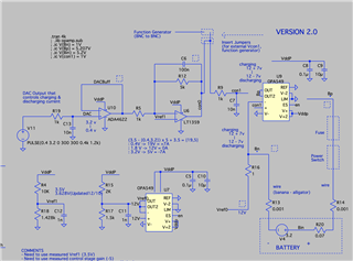
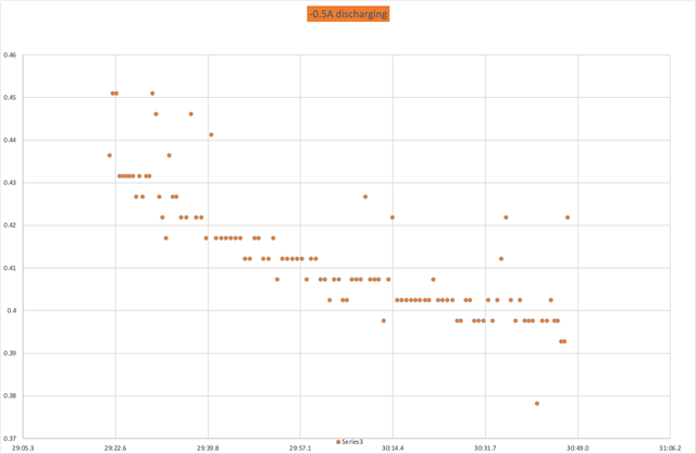
I have a reference voltage of 12 Volts provide by the bottom opamp, and this is biasing the Vref0 node to be 12V, and I have a upper opamp to biase the Bn node to biase the voltage so that I can either charge and discharge the battery by controlling the direction of current. For example for charging of 0.5A, I bias the Bn to be 12.5V, so that positive 0.5A current can flow through the battery. This charging operation is working as intended. However, when I bias the Bn node to be 11.5V to discharge the battery for 0.5A(so current direction is reversed), the power supply is pulling 1A when it should be pulling 0.5A. The power supply I am using is capable of supplying 6As at 30V, so that is not the issue for the supply. I am just wondering what could be the case for this issue?. In summary, when I discharge the battery, the power supply is pulling double the current that I intended to pull. If it works for one direction, it should work for other direction as well right? When this happens, the Bn node is still biased correctly, but drawing currents starts decreasing as shown in the graph below, but charging seems to be fine. Could you help me address this issue for me?
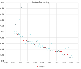
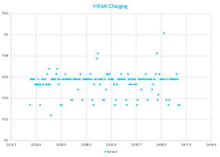
Any input of your expertise would be greatly appreciated

Thank you so much

Young

  • Hi Young,

    This is an unusual way to charge batteries, typically the current is measured directly and voltage is controlled through a separate loop.  But, I understand what you are trying to do.

    What is the voltage at the inverting input node in the two different charging cases?

    Regards,
    Mike

  • Hello,

    Thank you for your patiences, I ran more tests, and I can provide with more detailed data.

    When the current is set for -0.5 discharging. Reference voltage reads 11.78V, Bn(inverting node) reads 11.36. Bp is 15.13, and current is -0.402A(measured from Vref-Bn. Power supply is reading 0.85A which is double the current. 

    When the current is set for 0.5 charging Vref:11.91, Bn(inverging node) reads 12.35, Bp reads 16.26. Current is flowing from Bn to Vref so 12.25-11.91 = 0.44A

    The power supply reads the correct current. Also I keep noticing that when I set for current discharging. I keep losing the amount of current being put on the battery.

    Thank you for your time and effort

    Youngtae

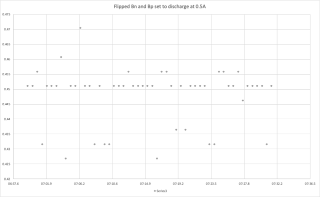
  • To follow up, I flipped Bn and Bp, so I am applying the same voltages as I would chage, but I flipped bn and bp, so the circuit is now discharging. When I did that the circuit does not pull extra current. It works as designed. I am really confused in what is going on with the circuit. 

    Thank you

    Youngtae

  • Hi Youngtae,

    From what you wrote in your first reply, you measured the current through R16, and it was roughly correct for both charging and discharging, is this correct?  So, the charging/discharging is correct, but it is just the measurement from the power supply that is incorrect?  Which power supply are you referring to?

    Regards,
    Mike

  • Hi Shin,

    Could you inform us what type of battery cell you are trying to charge and discharging?

    For Li+ battery, typical single cell voltage from ~2.8Vdc to 4.2Vdc. You schematic is shown 3.2Vdc, and it is likely Li+ battery is what you have. 

    For Li+ battery, the charging cycles are CC first, followed by CV charging, then terminate the charging cycles. Li+ battery is very sensitive to overcurrent in charging/discharging and overheating, because of low leakage current within the anode/cathode interfaces. 

    For NiCd type of battery, you have to implement CV first, following by trickle charging cycle (possibly to have CC, then CV and trickle charging depending on the battery chemistry). 

    For Pb acid battery, you have to do CV, followed by trickle charging cycle. 

    When you perform discharging of a battery, you have to discharge through external resistors or Electronic load. You should not discharge a battery by controlling the discharging current at 0.5A rate, because it will kill the battery (battery will overheat if you use battery as the dissipated load.). 

    You may perform cyclovoltammetry analysis by charging/discharging a battery above, but we are talking about low low current, and battery will likely not be overheating by cycling a battery in this manner, but not at ±0.5A rate and it may damage a battery due to overheating.

    If you have other questions, please let us know. 

    Best,

    Raymond