This thread has been locked.

If you have a related question, please click the "Ask a related question" button in the top right corner. The newly created question will be automatically linked to this question.

OPA2652: OFFSET at Input Pins and Unexpected Output

Part Number: OPA2652

We have made the connections as a non inverting amplifier. The circuit is as shown:
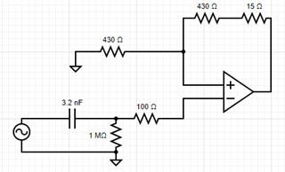
But in this configuration, we are observing a negative offset at the right end of the capacitor.

The output of the amplifier is as shown:
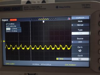
As its visible here, the output is negative offsetted and the negative half of the ac signal is being clipped off.

The input is 1KHz 1Vpp.

Why might this be happening?

  • Hello Prajwal,

    Your high-pass filter implemented with the 3.2nF capacitor and 1MOhm resistor are causing the offset.  If you try a 1.6uF capacitor and 2kOhm resistor, you will see very little offset and normal operation.  Because of the large resistor to GND, the amplifier inputs handle a distorted signal, affecting the feedback network and resulting Vout signal.

    If you try 640uF and 5kOhm resistor, you will see a smaller offset compared to 3.2nF and 1MOhm.  Please try your own resistor and capacitor combinations to generate a resulting signal you are comfortable with for your application.

    My circuit simulations were tested with 15 Ohm heavy load, 100 Ohm load, and 1kOhm (datasheet and reference design default) load.

    I would suggest selecting capacitor values between 32nF and 2uF, and selected resistor values between 100kOhms and 1kOhm.

    You can fix the behavior you are observing by addressing the high-pass filter at the op-amp input.  You may also consider using the second amplifier channel as an active high pass filter: https://www.electronics-tutorials.ws/filter/filter_6.html

    For either passive or active HPF, you should change your capacitor and resistor values.  

    Best,

    Alec

  • your input pins are drawn backwards, if connected that way, no reason it should work