Because of the holidays, TI E2E™ design support forum responses will be delayed from Dec. 25 through Jan. 2. Thank you for your patience.

This thread has been locked.

If you have a related question, please click the "Ask a related question" button in the top right corner. The newly created question will be automatically linked to this question.

TLE2082: TLE2082

Part Number: TLE2082

I have downloaded the SPICE model. I need to simulate the circuit by varying the input offset voltage and offset current and analyse the result. I couldn't find the parameter to change in the SPICE model. Please help

  • Hey Shamiya,

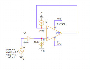
    Bias current and offset voltage can be added externally to the model if you would like to vary them. Digging through the netlist can be time consuming and is not worth it when there is an equivalent way to vary these parameters. I've included a screenshot below for reference.

    I1 and I2 will make up your input bias current, and the difference between them will make up your input offset current.

    V5 will be your offset voltage, this will add or subtract from your existing offset voltage depending on the polarity of the DC source and the polarity of the existing modeled offset voltage.

    Best.
    Jerry

  • I agree with your suggestion. I would like to know whether the SPICE model available have incorporated the offset parameter within it or not. If it is included, adding external offset sources will not give actual result. Please confirm

  • Hey Shamiya,

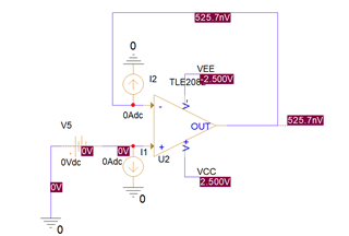
    You can test this with a buffer configuration. Running a bias point simulation and labeling the node voltages, you can see that the offset voltage is 525nV. The typical offset voltage of the TLE2082 is 700uV. This means that it's not modeled properly.

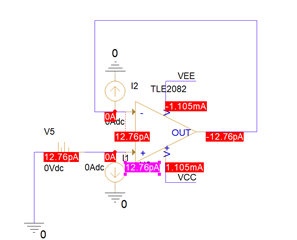
    Turning on the current labels, we can see that there is 12.76pA flowing into the inputs, which is close to what is expected for the device, but there is no input offset current, as both input bias currents are exactly matched. Varying I1 or I2 will create the offset current.

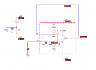
    Adding 700uV for V5, you can see this directly adds the offset voltage to the device.

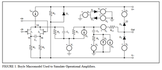
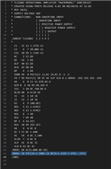
    You can now consider everything in the red box as your op amp with your bias current/offset voltage added. The place in the SPICE model that is responsible for your offset voltage and bias current is the matching of currents between the two input transistors (highlighted in the below picture). This architecture of macromodel uses a realistic input structure. However, the input stage calls JX for both input transistors and R3 and R4 in the picture are the same value. As such, the currents in the two branches will be equal, as will the gain and the "mismatch" so there will not be any offset voltage. You can change these parameters, but many other device parameters will change along with it. This is why it is simpler to add a DC offset voltage and DC bias current to your existing model.

    Best,
    Jerry