This thread has been locked.

If you have a related question, please click the "Ask a related question" button in the top right corner. The newly created question will be automatically linked to this question.

LMC6482: LMC6482 VS OPA171 question

Part Number: LMC6482
Other Parts Discussed in Thread: OPA171, , OPA2171, OPA2172, LMC6484

Hi Expert,

My customer using OPA171/2 some many long time and they trying to search our LMC6482 on his new application.

But some behavior different between both device , so they have some question want to know more detail comment or feedback as below;

(1) The manual states that lmc6482 is a CMOS operational amplifier. What type of operational amplifier is OPA2171? What is the structural difference between the two? What should you pay attention to during use? What should be considered when selecting devices?


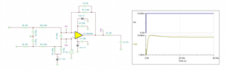
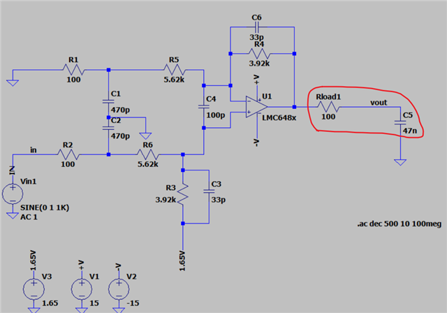
(2) Test the BODE diagram of the sampling circuit. The RC changes in the op amp output, such as 100R+47nF and 1K+4.7nF, have a greater impact on the LMC6482. But it has little impact on OPA2171 OPA2172.
I guess it has a lot to do with the internal structure of the op amp. I wonder what the difference is between the two?

(3) Vos of the op amp = 0.11mV. What is the role of the C4 capacitor and any helpful in here ?

(4) In the picture above, should C3 be connected to 1.65V or Gnd? What is the difference?

Eddie

  • Hi Eddie,

    1.) The OPA171 is also a CMOS amplifier. The two main differences between the LMC6484 and OPA171 are the input bias current (20fA vs 8pA typical) and the power supply voltage (15V vs 36V). There are of course many other differences such as the gain bandwidth (1.5MHz vs 3MHz), common-mode input voltage range, offset, etc.

    I see that in your simulation you have a +/-15V (30V) supply which violates the absolute maximum conditions of the LMC6484 and will destroy the device. The absolute maximum supply voltage for LMC6484 is 16V with the recommend maximum 15.5V.

    2.) 47nF presents a large capacitive load at the output of the amplifier. The 100Ω resistor and 47nF capacitor interacts with the output impedance of the amplifier, creating poles and zeros that effect the AC response of the circuit. The OPA171 has a lower output impedance than the LMC6484, and therefore the resulting RC pole and zero frequencies are extended outside the effective bandwidth of the amplifier circuit. Section 4 of this application note explains the relationship in detail: Determine Optimal Isolation Resistance for Driving Capacitive Load.

    The 100Ω isolation resistor should be sufficient for closed-loop stability. Injecting a small-signal step directly at the input pin shows the output voltage settles without oscillation.  

    LMC6484_47nF_CLoad.TSC

    3.) The C4 capacitor appears to be a common-mode filter.

    4.) R3 and C3 produce a low-pass filter response with the -3dB point at ~1.2MHz. it is appropriate to connect them in parallel as shown. 

    Regards,

    Zach