This thread has been locked.

If you have a related question, please click the "Ask a related question" button in the top right corner. The newly created question will be automatically linked to this question.

EMI/RF and low frequency analog

Other Parts Discussed in Thread: TPS63000, TPS61020, TPS60401, TLC2252, TLC2254

Hi-

I am trying to figure out a source of noise in the project I'm working on.  The signals I am amplifying are very low frequency, DC to about 3 Hz.  The noise is within this band so I can't filter it out.  The PCB is small, only about 3.5" X 2.5", 6 layer with power and ground planes and splits in the planes between the analog and digital sections.  Also on this same PCB are other analog signal chains, a processor, several small, lightly loaded TPSxx switching regulators, TPS7A4901DGN and TPS7A3001DGN linear regulators (to power the analog section), and a plug in 3rd party Bluetooth module.  The Bluetooth module is being used Class 2.

I am seeing very low frequency noise in the DC to 3 Hz band that seems to be correlated to RF transmit activity on the Bluetooth module.

I have recently read about EMI rejection ratio and how it can cause voltage offset errors in even low frequency and I am trying to rule out this as a source of the noise I am seeing.  The op amps in this signal chain are TLC2252AIPW (I'm also using TLC2254AIPW's elsewhere on this PCB).  Gain is about 5.  Do these parts have any known issues with EMI rejection or rectification of local RF sources causing noise or offset shifts?  There is also an INA from another vendor (I'm going to ask them these same questions).  Other parts in this same signal chain are an LM4040A41IDBZ reference and an ADS8326IDGK 16 bit ADC.  Could these also have EMI/RF sensitivities?

My other option is that power supplies are the source of this noise.  The PCB is powered by a Li-Ion battery.  A TPS61020 boost regulator and TPS60401 inverter supply the TPS7A4901 and the TPS7A3001 respectively which then provide power for the analog circuits.  A separate TPS63000 buck-boost regulator supplies the digital circuits and the Bluetooth module.  It is possible that current spikes drawn by the Bluetooth module as it is transmitting are causing the boost regulator and the buck-boost regulator to interact in some strange way. 

I'm leaning towards the EMI RR issue as being the cause however.

Thanks,

-Randy

  • Hi Randy,

    EMI could possibly be the issue. It is interesting that you see the correlation between RF transmission and the low frequency noise. Do you know where in the signal chain you are first seeing the noise and would you be able to capture an oscilloscope screenshot of it?

    It sounds like you have your eye on the TLC2252 and TLC2254 operational amplifiers. They are very reliable parts; however, they are older parts with no EMIRR characterization data for them at this time. They do not have built-in EMI filters like newer TI precisions op amps. The TLC2252/4 are CMOS based op amps and that gives them an advantage in EMI performance, compared to BJT based counter-parts which are more sensitive to EMI. Some things you can do to treat EMI are make you use decoupling capacitors on power supply inputs; placing them as close to the part as possible. You can filter your input signal above the range of your desired signal to try to remove high frequency and broadband noise. X2Y capacitors are excellent components to use for this type of filtering because they can replace multiple ceramic capacitors, have a low-ESL, and provide both common-mode and differential-mode filtering.

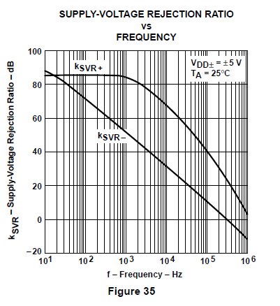
    I do see that you are using a lot of switching power-supplies, and the maximum switching frequencies of the TPS61020 and TPS63000 are in the ~1MHz range (720kHz and 1.5MHz, respectively). Looking on the datasheet of the TLC225x parts, I do see that the Power-Supply Rejection Ratio of these parts near 1MHz is not very high. See the figure below:

    It could be that the switching power-supplies are providing some switching-noise that is coupling into the power-supply of an op amp and creating an offset which shows up as noise. What kind of filtering is being used on the power supplies?

    Regards,
    Chris


  • Randy;

    Welcome to the world of frustration, aka "switching power supplies". Yes, I know that they are sometimes a necessary evil but the problems they can cause in low-level circuits can be aggravating.

    One potential problem when using multiple switching devices is that of the switching frequencies (or harmonics thereof) causing beat frequencies at a much lower frequency. Try substituting linear supplies temporarily and see if the problem remains. You have not mentioned the amplitude of your signal-- I'm assuming you have a small signal and high gain-- so things like thermal feedback or thermocouple effects in your PCB could possibly contribute problems.

    Shielding and filtering will eventually solve the most stubborn RFI/EMI problem but it may take lots of time and gray hairs to arrive at the solution. Good luck, Randy. 

  • Hi Randy,

    Have you have any luck eliminating the source of noise in your project?

    Regards,
    Chris

  • Hi, Randy.

    You should find noise source first. You should switch off all, except analog front-end and power supply for this. If noise are present, switch off power supply and use batteries for analog front-end supply. If noise are present, change system for measurements to galvanic isolated devices (ideal - IR data acquisition system with battery power supply without switching convertors). If this is not help, use electromagnetic shield. If this is not help too, analyse your schematic and simulate schematic in special software (for example, MicroCap). After you experiments, you should find the noise source: analog front-end, ambient conditions, power supply, microprocessor, bluetooth module or something else.

    P.S. Sorry for my bad english.