This thread has been locked.

If you have a related question, please click the "Ask a related question" button in the top right corner. The newly created question will be automatically linked to this question.

XTR111 - Loading Issue

Other Parts Discussed in Thread: XTR111, LM1117

Dear Sir,

         I am using XTR 111 to convert my 0-3V (PWM based DAC) as 4-20mA. I am powering the XTR111 using a LM1117 ADJ @ 9V/ 1A (12V as I/P). Also I had retained the same circuit as mentioned in your reference design (evaluation board). The MOSFET which I am using is IRFL9014 ( Pchannel, -60V , 1.8A) and the transistor is BC557 (PNP).

  The problem:

           I am loading the output of DRAIN (with 15E & 10nF), initially with 500E, with a constant Vin (1V). My current flow is constant. As I decrease my resistance further (400E, 300E, 200E, 100E), the current flow remains the same. But as I increase the resistance above 1K, the current flow decreases. I am unable to solve this problem.

What is the logic behind this? How to solve this? What parameters decide the loading limit of XTR111?

  Output of the 4-20mA will be fed to a system which will have a load resistance of more than 100K.

Kindly reply me.

With regards,

Jayaraj.A


  • Jayaraj.A,

    Current sources are limited by their compliance voltage limit, the maximum voltage they can supply. For the XTR111, the compliance voltage limit is 2V below the positive power supply. In your case, if the output current times the load resistance is greater than approximately 7V, the current will not be properly regulated.

    Note that the compliance voltage required for a 100k load at 20mA would be 2000V. To receive a 4-20mA input it is probably intended that you add a resistor to the input of your receiving system--100 ohms is common. This would produce 2V at 20mA which would be within the compliance range of the XTR111.

    Regards, Bruce.

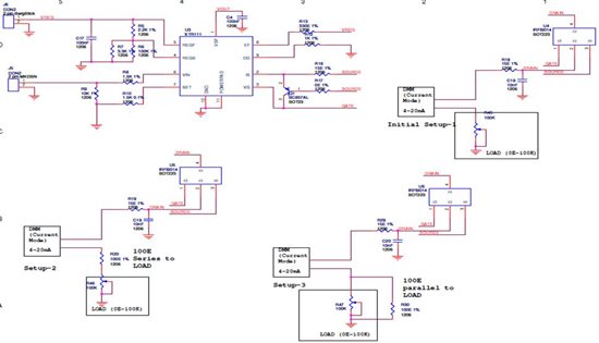
  • Dear Sir, Thanks for your reply. As per your suggestion, I connected a 100E resistance in series to the load of 100K (Potentiometer). My setup 2 diagram indicates the 100E put in series to the load. I didn’t find much improvement. As my resistance increases above 1K, my current regulation stops (decreases). Also I had connected a 100E resistance in parallel to the load of 100K (Potentiometer). My setup 3 diagram indicates the 100E put in parallel to the load. I didn’t find much improvement. As my resistance increases above 1K, my current regulation stops (decreases). My XTR111 works on the supply of 9V/ 0.6A and the input control voltage is 0-3V ( 0-20mA). So kindly reply me where to add a resistance of 100E to my load as per your mail. Is it on the source side of the MOSFET? R16? Or else some other better solution to avoid this issue? With regards, Jayaraj.A

  • Hello Jayaraj,

    Perhaps you've misinterpreted what my colleague Bruce has stated.

    I order to properly drive a 20mA signal into a 100k load you would have to have a compliance voltage of at least V=100000Ohms*0.02A = 2000V.  You are supplying the XTR111 with 9V, therefore this will not work.   

    The suggestion was to reduce the load resistance from 100kOhm to100Ohm.  With a 100Ohm load resistor, the max output voltage is only 2V which is within the compliance limits of the XTR111.  Placing the 100Ohm resistor in parallel with the 100k resistor should have produced correct results because the effective resistance of the load would have been reduced to roughly 100Ohms. 

    What type of application are you building that needs the 4-20mA loop to be terminated into a 100kOhm resistor? 

    Unfortunately the figures you've inserted did not get processed correctly and I can not see them.

    Regards,
    Collin Wells
    Precision Analog

  • Dear Sir,

         Thanks for your reply. So I will conclude that XTR111 will be regulating its output current, only if it is within its compliance voltage. I will keep my output load, within that voltage range. 

          Kindly have a view on my circuit and reply me if there is any bug. I will finalize with my set up 3 diagram, even if my load is more (10K or 100K) by paralleling a 100E or less than that.

          My application: Weighing Scale to PLC. Weighing Scale - ADC counts are converted to analog voltage of 0-3V, fed to XTR111 and expecting the 4-20mA (constant).

        1. What will be the input resistance (impedence) of general PLC's? (I assumed a high input impedence in terms of kiloohms)

         2. Also what is the maximum current consumed by XTR111 for the load regulation? I am tapping a 12V unregulated DC and feeding to regulator (LM1117 ADJ)  of 9V, which is given as supply to XTR111. Is this supply a good option? or you want to increase the 9V?

         3. To obtain my logic of variable load of 10K or 100K to a constant 4-20mA (XTR111), could you suggest any additional circuit ( op amp based) on the output of XTR111?

               Any additional circuit on the output of XTR111, with 10K/100K load, will give the current regulation?


    Kindly reply me so that I can finalize my design and commit to the customer.


  • Hello Jayaraj,

    Yes you are correct, the XTR111 can only maintain the correct output current if the output voltage is within the compliance limits.

    Unfortunately I can not read your schematic.  Would you please upload a higher resolution version as a file instead of uploading it as an image?  That way the forum won't compress it to fit the page. 

    1.)  I am not a PLC expert, but the resistances I have seen are in the range of a few hundred ohms.  250R produces 1V- 5V from 4-20mA.  221R or 223R produces around 4.5V for the 20mA level so it would be away from the rails for a 5V data acquisition system.

    2.)  The maximum quiescent current of the XTR111 is listed in the datasheet as 300uA over the full temperature range.  The datasheet specifications for the XTR111 were obtained with a 24V supply.  Deviations away from that supply voltage will result in power-supply rejection related errors.  Specifications that will be affected by the change in power supply voltage include:  Input offset, Vref accuracy, Vreg accuracy. 

    Here is an example showing the effect of the power supply on the max input offset voltage:  
    The max input offset voltage of +/-250uV will change a max of 2uV/V when the power supply deviates away from 24V.  So, (24V - 9V) = 15V * 2uV/V = 30uV.  So with a supply of 9V, the max input offset voltage could be up to +/-280uV.

    Also, your supply voltage will dictate the current source's compliance voltage.  The higher voltage you supply the XTR111, the higher your load resistance can be without hitting compliance and loosing output regulation.

    3.)  As mentioned in the previous post you will be bound by the supply voltage rails of your current sourcing solution to meet such a high compliance voltage.  If you have a >2000V supply available that you can bias your current source off then there may be a solution available.

    Please let me know if you have additional questions.

    Regards,
    Collin Wells
    Precision Analog


  • Hello Jayaraj,

    Yes you are correct, the XTR111 can only maintain the correct output current if the output voltage is within the compliance limits.

    Unfortunately I can not read your schematic.  Would you please upload a higher resolution version as a file instead of uploading it as an image?  That way the forum won't compress it to fit the page. 

    1.)  I am not a PLC expert, but the resistances I have seen are in the range of a few hundred ohms.  250R produces 1V- 5V from 4-20mA.  221R or 223R produces around 4.5V for the 20mA level so it would be away from the rails for a 5V data acquisition system.

    2.)  The maximum quiescent current of the XTR111 is listed in the datasheet as 300uA over the full temperature range.  The datasheet specifications for the XTR111 were obtained with a 24V supply.  Deviations away from that supply voltage will result in power-supply rejection related errors.  Specifications that will be affected by the change in power supply voltage include:  Input offset, Vref accuracy, Vreg accuracy. 

    Here is an example showing the effect of the power supply on the max input offset voltage:  
    The max input offset voltage of +/-250uV will change a max of 2uV/V when the power supply deviates away from 24V.  So, (24V - 9V) = 15V * 2uV/V = 30uV.  So with a supply of 9V, the max input offset voltage could be up to +/-280uV.

    Also, your supply voltage will dictate the current source's compliance voltage.  The higher voltage you supply the XTR111, the higher your load resistance can be without hitting compliance and loosing output regulation.

    3.)  As mentioned in the previous post, you will be bound by the supply voltage rails of your current sourcing solution to meet such a high compliance voltage.  If you have a >2000V supply available that you can bias your current source off then there may be a solution available.

    Please let me know if you have additional questions.

    Regards,
    Collin Wells
    Precision Analog