This thread has been locked.

If you have a related question, please click the "Ask a related question" button in the top right corner. The newly created question will be automatically linked to this question.

INA128: INA128

Part Number: INA128

Good morning Sir

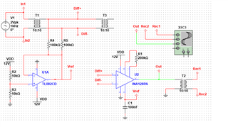
I would like to monitor a floating audio signal (the signal exists on the common part of 2 transformer) 
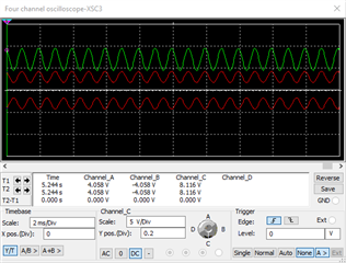
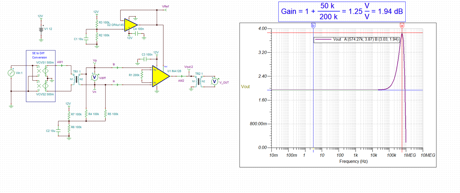
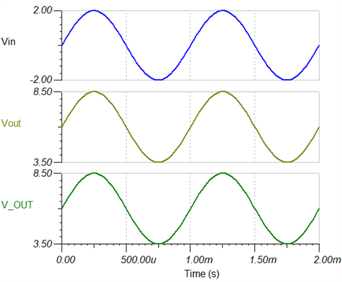
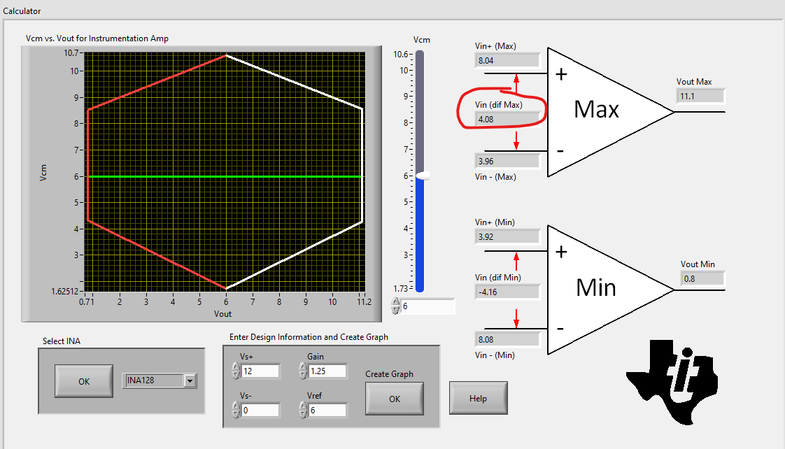
Because I want to use only 12VDC single supply, I made the midpoint Vref by using 2 resistors R2 and R3, buffered by U1A and use this Vref for the ref pin of INA128. I also use R4 and R5 as the return path for 2 inputs of INA128. Simulating this circuit on MultiSim, it seems evrything is OK but I am not sure about the value of R2, R3, R4 and R5.

Can you help me with some advice?

Thak you and best regards,

Tuan Tran

  • Hello, 

    I have put the circuit into Tina in order to better understand the design and help guide our discussion. Below I am getting a gain of 1.94 dB and this aligns with the expected calculated value. I have modified the circuit such that the reference buffer is only driving the reference pin. I have included a voltage divider from the 12 V power supply to provide the 6 V midpoint at the input. I have also included 10 uF low pass capacitors at both voltage dividers to clean up the DC voltage being supplied at these nodes. If the power supply is clean you may decide to leave these capacitors as placeholders or change their value. They will require an RC startup when the circuit is powered on. The 100k resistors are not really contributing much to the noise in this low gain design and I don't see an issue with using them. In higher gains the INA has much lower noise and the resistors should be lowered if you plan to use the INA in higher gains. Lowering the resistors will increase the power consumption. 

    Using our free online engineers calculator that can be found here:

    https://www.ti.com/tool/ANALOG-ENGINEER-CALC

    I am finding that the max differential input signal will be +/-4.08 V. I do not see an issue with the DC biasing you have. 

    When transformers are present in a design it is usually a good idea to consider adding place holders for over voltage protection on the printed circuit board in the event that you may need to use over voltage protection. Inductive elements and fast dv/dt transient events can create undesirable voltage levels in circuits. We have a training series on electrical over stress that covers this topic that can be found here:

    https://www.ti.com/video/series/precision-labs/ti-precision-labs-op-amps.html

    I hope this information is helpful. I have included my simulation below. 

    8228.INA128.TSC

    Best Regards, 

    Chris Featherstone