This thread has been locked.

If you have a related question, please click the "Ask a related question" button in the top right corner. The newly created question will be automatically linked to this question.

TL074H: TL074H

Part Number: TL074H
Other Parts Discussed in Thread: TL074, TL074M,

I have had several of these IC burn up.

I am using +24VDC (V+) and -15VDC (V-) so the Vs(V+ - V-) = 39V

The recommended max is 40V and the absolute max is 42V so I know I am at the upper side but I am under the recommendation, so why am I having the IC burn up in equipment at 25 degree C environment ???

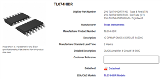
I know the TL074M is only rated for a max Vs of 30V but I am not using the M version as from the photo you can clearly see the part number of H after the TL074 of the IC that is not burn.

  • Hi Abner, 

    Could you please share with us how you were configuring the part? If possible a schematic would be helpful. 

    Also, if you have the TI reel to show us what units were used to, could you share that? 

    Please let me know if you have any questions.
    Thank you!

    Best Regards,
    Ashley

  • Hello Ashley,

    As for the reel information I am doubtful I will find any, but I will look for any available info.

    The TL074H IC is being used as a simple voltage follower. We have several in order to connect to a 64 channel DAC board.

    Since we test products at 15V and our measurement DAC board only handles 10V range we use the TL074H as the voltage follower for each channel and at the output place a voltage divider resistor circuit (10kOhm + 10kOhm) afterwards before the DAC board (has its own input resistance). In the circuit below Vp (V+) is +24V and Vn (V-) is -15VDC. The AD# is a 4way measurement from the test product and input to the voltage follower using the TL074H, ADA# goes to the voltage divider and ACH# goes to the DAC. Its a very simple setup and neither the test product nor the DAC board is getting damaged, only a random TL074H IC.

    Each Vp (V+) has a 0.1uF cap

    Thx,

    Abner

  • Hi Abner, 

    Is there any pattern to which TL074H unit is getting damaged of the 4 units on the board? You mention a random IC getting damaged - which one has been damaged so far? 

    Has the supply voltage pins been monitored to check if it goes beyond the expected values? I am assuming all TL074H devices share the same Vp and Vn trace? 

    Regards,
    Ashley

  • Hi Ashely,

    Sorry for the delay, I confirmed the power supply to be ok on both the +24VDC & -15VDC as each board has a dedicated voltage regulator on board.

    There are not 4 units on the board, instead there are 16 units (to get the 64 channels) and all share the same Vp & Vn

    So far I have confirmed the U37 being damaged on 2 separate boards and I am pending to get in the other damaged boards in my office later on.

    I still don't have any reel information.

    Can you please confirm if the TL074H can handle 40V for normal operation?

    Or does it need to follow the 30V for normal operation?

    Thx,

    Abner

  • Hi Abner, 

    The TL074H can operate up to 40V total supply, which is why I was asking for the TI reel information to confirm that you were using the correct device in damaged parts of the board. Could there also have been any assembly issues that would have shorted any of the pins?

    What is being connected directly to the inputs of each of the op amps?

    Regards,
    Ashley

  • Hi Ashley,

    I do not have any reel information, but here is what was ordered from Digi-key "296-TL074HIDRCT-ND / IC" which references a TI part we are discussing.

    As for shorts the only ones you see are to implement the closed loop voltage follower, personally I would have used traces, but I didn't design the board.

    Keep in mind this is used in a 24/7 environment and the ICs were on for several months prior to the thermal breakdown, always in a climate controlled environment.

    The inputs of the Op-Amps are used in a 4-way measurement for a device under test with voltages from 0 - 15VDC. So there should be no high currents going directly to the Op-Amp itself as the current will go to separate loads and the Op-Amps are in parallel with the loads to make the 4-way measurement. Given an Op-Amp in the closed loop voltage follower mode is high impedance then any current flowing to it will depend on how high the impedance really is.

    Can you confirm the high impedance of the Op-Amp, I could only find the impedance for the open loop and not the closed loop implementation.

    Thx,

    Ab

  • Seems the input resistance is listed as 10^12 so it is high enough so no major current is pulled by the OpAmp in the voltage follower mode.

    All input signals are in the acceptable range of the rails

    And the output is immediately limited by the 10k resistor so even if there was a short afterwards going to the DAQ the current would barley be a few mA when the short circuit rating of the OpAmp is 26mA.

    I'm just going to change the Vn from -15V to -5V as I'm only requiring 0-15V for my testing and -5V as Vn should be enough for the OpAmp to pass GND.

    This way total Vs is 29V and I will continue to monitor 

  • Hi Abner, 

    Thank you for the additional information. I agree it would be helpful to see if changing the supply voltage impacts the failure. Based on the pictures, it does look like the damage area is localized around the Vcc pin, so it may be coming from something with the power supply. 

    Do you have design files that can be shared? We would like to understand how the board layout was designed, specifically for this op amp section. 

    Thank you!
    Best Regards,
    Ashley

  • Hi Abner, 

    Has this issue been resolved or are there further questions or comments to this thread? In the meantime, I will mark this thread as "TI Thinks Resolved" but please let us know if there are any questions. 

    Thank you!
    Best Regards,
    Ashley