This thread has been locked.

If you have a related question, please click the "Ask a related question" button in the top right corner. The newly created question will be automatically linked to this question.

THS4505: Simulation and implementation results coming different

Part Number: THS4505
Other Parts Discussed in Thread: THS4509

I designed Band Pass Filter using THS4505 Fully Differential Amplifier . The simulation in TINA gives gain vs frequency plot as per R,C values selected for the band. But when same design is implemented in breadboard and output was  observed in MSO, the plot do not match with simulation. How to match both results?

  • Hi Vinay,

    Can you share the simulation file that you created or a schematic so that I can replicate the simulation? Also, what is the pass band range of the band pass filter?

    It would also be helpful if you could share the observed results from your implementation.

    Thanks,

    Nick

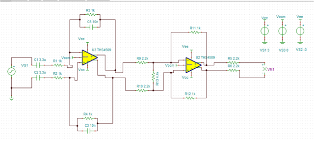
  • The simulation circuit  

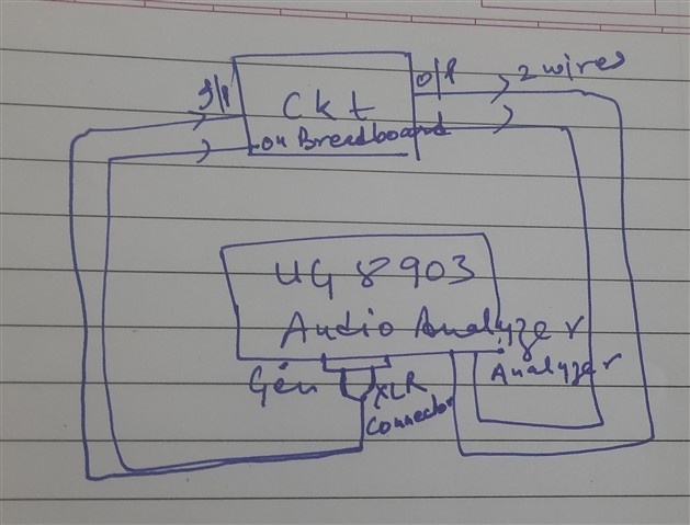
    and the measurement setup is as above.

    The Vrms values at audio analyzer were measured they are 0.4 Vrms  at 100 Hz , increases slightly till 31 KHz and then drop.

    The levels are coming lesser than simulation and fiter characteristics also not coming. Pls suggest what is to be rectified in breadboard implementation. The input level was set at 2.94 Vp in simulation and 2.1 Vrms during testing

  • Hi Vinay,

    Thank you for sharing this information! Can you first confirm, are you using THS4505 or THS4505? In your original post you say you are using THS4505 but the simulation uses THS4509.

    Can you provide a few further clarifications:

    1. What is the waveform (i.e. sine wave, square wave, unit step, pulse) and frequency you are assigning VG1 in your simulation?

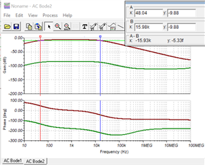
    2. What is the passband range you are anticipating? I did a couple quick calculations based on the component values in your simulation and I see a pass band range of about 50Hz to 16kHz. When I run this in simulation, I see similar results as shown below.

    We do not recommend testing high speed amplifiers on breadboards because the stray capacitance of the breadboard could significantly effect the device performance and circuit behavior.

    Thanks,

    Nick