This thread has been locked.

If you have a related question, please click the "Ask a related question" button in the top right corner. The newly created question will be automatically linked to this question.

LM2901AV: LM2901AV output signal transition problem

Part Number: LM2901AV
Other Parts Discussed in Thread: LM339LV, LM2901

Hi Expert,

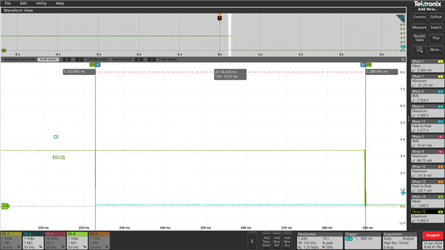
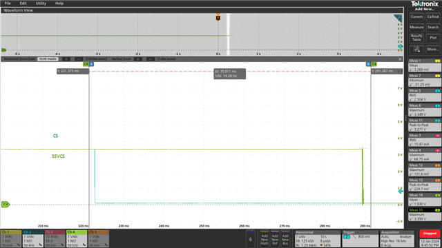
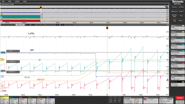
I have a question about the transition state of LM2901AVQPWR. The following is the circuit diagram of our model, but I found that if 55VCS and CS are connected together and then 3.3V Turn on, I find that the comparator output pin2 (55VCS) and Pin1 (CS ) will have a time difference of 66ms. Please tell me that this IC contains four comparators, but if the input signals are simultaneous in the application, will there be a time difference in the output
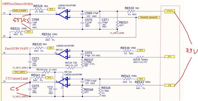
Eddie

  • What is VCC_MCU? The common-mode input-voltage range is specified as 0 V to VCC − 2 V. If any input voltage is larger than VCC − 2 V, the electrical characteristics are no longer guaranteed. If this is your problem, then you should use comparators with rail-to-rail inputs like the LM339LV‍PWR.

  • Clemens

    Thanks for your continued support of the forum.

    Eddie

    Thanks for your post.  Clemens made a valid point.  If you need further assistance, please include waveforms including the inputs and output which shows what you are describing.  We are on holiday break today and will review any new posts on Tuesday.

    Chuck

  • Hi Expert, 

    the mcu_vcc is 12v supply.

    Is that setting will any impact  on output signal delay issue?

    Eddie

  • With a 12 V supply, 3.3 V signals are fine.

    Please provide an oscilloscope trace of the two inputs and the output.

  • Hi Expert,

    Please refer to attachment

  • Chao,

    Are these the output signals? Do you have scopeshots at the input pins of the comparator? 

    I also noticed for the M512B comparator, there are 3 input caps but M512A only has the 1 input cap. These would contribute to the different time delays on the input. What are these caps for? I would remove them anyways especially C569 and C591 as these just slow down the signals and inject noise. If you need filtering on the inputs, I wouild recommend adding hysteresis instead. 

  • Hi Expert,

    My customer have another question about spike signal input and output reflection capability.

    They use LM2901 for current protect and they will be faced the peak current as pic like triangle waveform.(blue one and black one is reference)

    But the LM2901 output signal seems can not reflection when peak current signal input.

    and we see this spike input signal just 2us , Is that make sense for LM2901 reflection by output side ?

    If not , do you have any new device suggestion for this application ?


    Eddie

  • Hi Eddie,

    Remove C591 - it is slowing the edges. The time constant of 470pF and ~20k is 9.4us - so you are artificially slowing the input signal. It is generally a not a good idea to place a capacitor between the inputs to "filter". As Chi mentioned...better to add hysteresis if there is too much "chatter".

    If VCC_MCU is 12V, then the input limit is 10V. Ensure that the input pulses stay below 10V, and also ensure that the pulses are not going below ground.