This thread has been locked.

If you have a related question, please click the "Ask a related question" button in the top right corner. The newly created question will be automatically linked to this question.

INA214: Circuit Design for Current Measurement: INA214 or OP-AMP

Part Number: INA214
Other Parts Discussed in Thread: INA190, INA186, INA228, INA229, INA138, INA181

HI, Ti Team

I need a solution for current measurement. I want to design a circuit with a gain of 5.

  1. The GAIN of INA214 is 100 V/V, but is it acceptable to connect a 190kΩ resistor on the input side(IN+,IN-) to lower the GAIN to 5?
  2. Between using INA and using an OP-AMP, which one is more precise for current measurement?
Regard.
Jeong.
  • Hello Yongki,

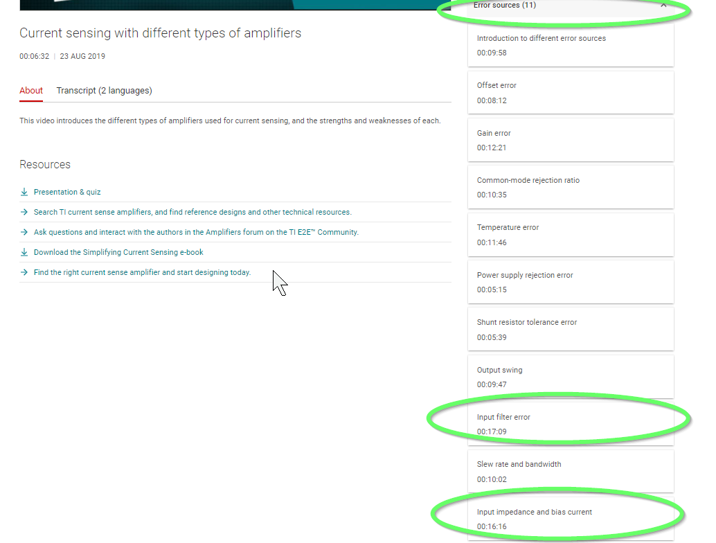
    So there are tradeoffs.  The INA214 has much higher common mode than most opamps.  Here are some tradeoffs described.  https://www.ti.com/video/series/precision-labs/ti-precision-labs-current-sense-amplifiers.html

    From your comment of using the 190kΩ I assume it is for a small current.  The INA214 has µA of input bias current so this would not work.  If you were using a current sense amplifier I would go with some thing like the INA190 or INA186 as they have low input bias current.  The VCM is not as high as the INA214.  If you need that VCM range then I would suggest one of our digital power monitors like the INA228/INA229.  There are other versions with variation of accuracy.

    Regards,

    Javier

  • Hi, Javier

    Thank you for your insightful comments.

    The plan has changed, and I need a Current Monitor with a GAIN of "10" to measure the current of 9V voltage.

    1. Is it possible to use INA214 with a "90"kohm series resistor together?
      1. The current through the input vias is calculated to be 8.17mA based on a 9V input.
      2. Sensing resistance = 10 ohm (no mili) / Max Current = 40mA.
    2. What precautions should be taken when using INA Series and series resistor?
    3. Can INA190A3 be a pin-to-pin replacement for INA214? 
      1. I currently use INA214 in another product, and if 190A3 can replace 214, I would like to manage inventory with one component.
      2. Normal Application, Package: SC70, Output: Max 3V
    4. The VCM for INA214 is 12V, and for INA190, it is 40V. Does INA214 have a wider range?

    Regards.

    Jeong

  • Hello Yongki,

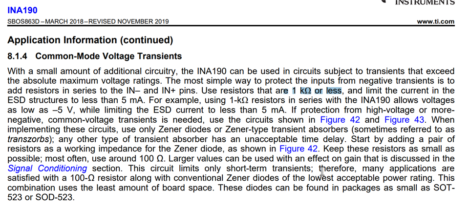
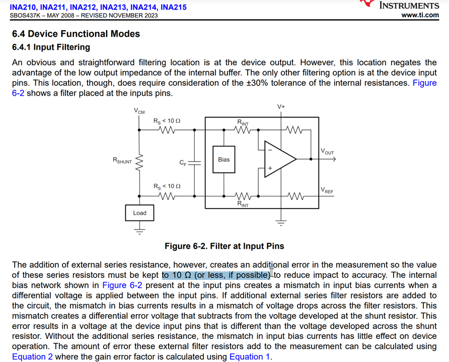
    A series resistance that large is not recommended.  See the input filtering section in the datasheet for the INA214 and INA190.  You need to let me know the accuracy and the minimum current that needs to  be measured.

    The input bias current is normally the issue with a series resistors.  This will cause a gain error.  Yes those two devices are pin to pin.  The INA214 VCM is 26V and the INA1901 can go to 40V.  I had mistaken the INA214 above.

    https://www.ti.com/video/series/precision-labs/ti-precision-labs-current-sense-amplifiers.html

    Look at these videos in the error sources section:  Input Filtering and Input impedance and bias current

    Regards,

    Jaiver

  • Hi, Javier

    Source Voltage : 9V
    Sensing Resistor : 10ohm
    Max Load Current : 50mA
    Min Load Current : 15mA
    GAIN : 10

    Expected Ideal Output Voltage : MAX 5V / MIN 1.5V

    System Discription

    1. I want to confirm the Off state through current measurement. (Off: Iload = 0mA / On: Iload = 15~50mA)

    2. Since I need to control a FET with the output, it should be 1V or higher when 15mA is flowing.

    3. It should be determined as Off when the output is below 1V.

    Question)

    The Current Output product (INA138) allows adjusting the Gain from 1 to 100.

    • How suitable is using a Current Output product for my application?
    • Please let me know the advantages and disadvantages of Current Output products and Voltage Output products.
    • Is a Buffer necessary when connecting a Current Output product to a FET or MCU ADC?

    Regards.

    Jeong

  • Hello Yong,

    1.  For confirming the off state we need to make sure the offset will be good enough.  So the INA138 will grab current from Vin + and can be upto 100µA depending on the input voltage.  0.5V is max input differential voltage.

    2.  The output current limitation is the issue for the INA138.  Depending on the FET used and its leakage.

    3.  Offset is not an issue as 2mV offset is worse for the INA138 which is 2mV/10Ω = 200µA

    If you could change your shunt resistor to 4Ω then I would use the INA190 or INA186 due to the low IB and lower VOS.  If you must go with the 10Ω and need the gain 10 then the INA138 is an option but you must realize the output is a current and must not have a leakage therefore needing a buffer like you mentioned.  

    Advantage of the current output is the adjustable gain and adding currents from multiple INA138.  The downfall is the IB is used to power the output FET and will change with Vsense and leakage at the output not going through the Rshunt will give you and error.  If all you need is a transition to on and off and you can use lower accuracy you could even use the INA181.