This thread has been locked.

If you have a related question, please click the "Ask a related question" button in the top right corner. The newly created question will be automatically linked to this question.

Current sense part recommendation inquiry

Other Parts Discussed in Thread: INA241B, INA240, INA281, INA293, INA186, INA214, INA181

Hi, TI expert

The customer is currently developing a temperature controller for use with the heating mat.

The customer is currently using a method of linear temperature detection by employing NTC thermistors for temperature measurement.

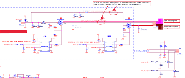
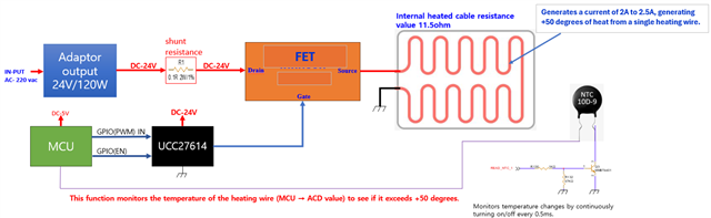
However, the customer wants to configure a circuit that deviates from the conventional NTC thermistor usage. They aim to use a shunt resistor to measure the current, read it in the MCU, and convert it into temperature values.

In the schematic below, I would like to apply the circuit between the FET and the heating-wire.

Is there any recommended solution you could suggest for this?

If there are any recommendations for components such as current sense or others, as well as reference circuits, that would be appreciated.

Please check. Thank you.

  • Hello Appreciated Engineer,

    I am looking this over and will respond shortly.

    Sincerely,

    Peter

  • Hello Mr. Lee,

    The schematic indicates the current-sense amplifier measuring the shunt would see a input voltage that is switching from 24V to ~0V. Thus, I would lean toward recommending devices with good Vcm (common-mode voltage) PWM rejection (INA241B or A, INA240) or even just very good AC CMRR (INA296, INA281, INA293, INA310).

    However, the need for enhanced PWM rejection or high CMR may depend on how low the duty cycle is. For example, if you need an amplifier output measurement to settle within 1ms, then the INA214, INA186, INA181 may be suitable options. However, these devices have survivable input Vcm's of -0.3V. Thus, using these in switching applications with possibility of inductive kick back pushing Vcm <-0.3V poses a damage risk and thus may require input pin protection (current-limiting resistors and/or Schottky diodes).

    I would assume you would need a device/circuit with low drift, high gain, low noise, all in an effort to resolve differences in current changes that indicate sufficient heating of the element.

    The most important things to know in choosing the optimal device is:

    1. What is the required output measurement settling time assuming this is a PWM application?

    2. What is power budget available for the amplifier? What are the available power supplies?

    3. What is the required signal bandwidth?

    4. What is the maximum allowable shunt resistor power dissipation?

    Given the possibility of inductive kickback, my first-pass recommendation is the INA281x5/INA293x5 (same device, but with different error specifications) due to excellent CMRR, error, and high gain and bandwidth, which can be helpful in driving ADCs without the need for a buffer. The only downside to this device is that is the bandwidth decreases with lower currents (See Figure 6-1 of datasheet).

    If the INA281's Vcm step response is too slow (see Figure 5-23), then consider the INA240 or INA241, where INA241 will have better bandwidth and slew rate among other things.

    Here is some literature:

    https://www.ti.com/lit/ab/sboa187e/sboa187e.pdf

    https://www.ti.com/lit/an/sboa172/sboa172.pdf

    https://www.ti.com/lit/ab/sboa160d/sboa160d.pdf

    https://www.ti.com/lit/ab/sboa174d/sboa174d.pdf

    https://www.ti.com/lit/an/sboa562/sboa562.pdf 

    Sincerely,

    Peter