This thread has been locked.

If you have a related question, please click the "Ask a related question" button in the top right corner. The newly created question will be automatically linked to this question.

XTR115: 2-wire XTR115UA swing when walki talkis are used or load is switched

Part Number: XTR115
Other Parts Discussed in Thread: XTR117

Hi,

I have tried to set up a 4..20mA analog output signal with the XTR115.

Everything works so far. However, I seem to have EMC problems.

If a walki talki or a consumer is connected nearby, the output of the current loop oscillates.

It can be simulated very nicely if you go with the walki talki directly to the line next to the circuit I get the output signal pulled down to 0mA.

I have already tried the ferrite beads, the cap and TVS-diode from the recomendet designs, but nothing seems to help.
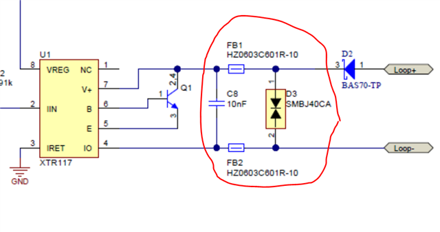
Can anyone tell me what I have done wrong and how I can perhaps increase the interference resistance?

  • Eduard,

    1. To some degree all amplifiers and other devices with an analog input or output convert RF interference to an offset shift.  Many amplifiers include a parameter called EMIRR (Electromagnetic Interference Rejection Ratio).  See EMI Rejection Ratio of Operational Amplifiers for details on the mechanism that converts RF interference to offset shift.  Unfortunately, the XTR115 does not specify this parameter.
    2. It is possible that the interference issue could be pickup on the XTR115 input, power supply, or output.  It is also possible that the RF pickup is happening on the LDO or on the DAC.  One way to better understand the issue would be to use long leads on the loop supply and apply the interference to the ends of the leads.  This would make sure that the interference signal is mainly applied to the XTR115 output as opposed to near the entire module where the other elements in the system receive interference as well.
    3. It is generally more common that the sensitive node for devices is the input as opposed to the output.  If the XTR115 input is sensitive, you could add a filter on pin 2.  This document Using the XTR115 with the PGA309 provides details on the filter selection.
    4. Your ferrite filter actually looks like a good approach.  If you can afford some drop in the loop, you could add a small series resistance.  Keep in mind that the ferrite is only a high impedance over a limited frequency range.  Using two 10 ohm resistors in series with the ferrites (20 ohm total), would set a cutoff of 796kHz and only drop 0.4V full scale.  Even if this is not a practical solution, you might try replacing the ferrites with fixed resistors and try different values to see if the problem improves.  This is another way of determinizing if the issue is at the XTR output, because if a low cutoff frequency filter on the output should solve the issue. 
    5. The XTR117 was tested for EMC.  This device is very similar to XTR115 (minor design spin).  The documentation of the design that passed EMC and EMC results are available here:  https://www.ti.com/tool/TIPD126 .  Also, I have not seen many EMC issues with the XTR series.  They are designed to have very long cables so in general I would expect that they are exposed to significant interference coupled to the output via the cables.  This E2E post ( e2e on XTR EMC ) covers one EMC issue with XTR and the customer solved the issue with filtering the XTR input (output of previous stage ).  
    6. PCB layout can impact the issue as well.  It is possible that some issues in the layout can make some traces act as antenna.  If this is the case, filtering may not be as effective.  It is hard to summarize in a short post all the PCB layout precautions that can be used to minimize RF pickup.  Below is a video series that convers the topic in detail.  In the series I would focus on sections a, b, c, and e.  One of the most common issues is a slot antenna that is covered in section 3.
      1. Intro to PCB for good EMC

      2. Trace as wave guide

      3. Stackup impact on performance

      4. PCB trace impedance matching

      5. Crosstalk on PCB layouts

      6. Decoupling capacitors

      7. Data integrity issues

      8. Electromagnetic compatibility testing methods and standards

        Best regards, Art