This thread has been locked.

If you have a related question, please click the "Ask a related question" button in the top right corner. The newly created question will be automatically linked to this question.

INA180: Measure BTL loudspeaker current from class D amplifier

Part Number: INA180
Other Parts Discussed in Thread: INA168, INA240

Hi! 

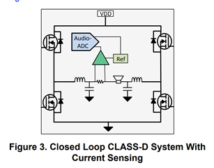
I have been investigating ways to measure loudspeaker current connected in a bridge-tied-load fashion to a class D amplifier. 

Following the excellent  SLYA031, I have decided on placing my shunt post the LC filter (https://www.ti.com/lit/ab/slya031a/slya031a.pdf)

I am really only interested in a low-passed current response, hence I do not care for bi-directional sensing.

My question is: why should it not be possible to choose the INA180 for this application? With the BTL architecture, I expect the common-modes to stay above 0 - but I might be wrong here. In that case, would adding some input resistors and accepting the gain error degradation be of any good?

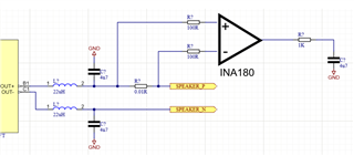
So far, my suggestion for a schematic looks like this:

  • Hi ElectroLolz,

    I will take a closer look at this and get back to you by tomorrow.

    Best,

    Angel

  • Hi Angel, 

    Thanks, looking forward to it Slight smile Please tell me if you need more details.

    Best regards, 

    Lolz

  • Hi Lolz,

    Is there a reason why you want to use the INA180 in particular?

    This design recommends using INA240 or alternate devices such as the INA241 or o the INA168.

    I'm not too familiar with this application, but my guess is that these devices are recommended because they have a higher bandwidth.

    This is important for switched-node environments where the common mode transients will have large dv/dt signals.

    INA180 at 350kHz has less than half of the bandwidth that INA168 offers for example. 

    The input offset of INA180 is also quite higher at 150uV compared to 25uV, which means that you won't be able to measure low current values as accurately with this device. 

    INA240 also allows Vcm to go all the way down to -4V which gives you a better margin compared to INA180. 

    Do you know what the range of currents that your system will be measuring is? This information is useful in selecting the appropriate shunt resistor value.

    The input resistors in your schematic may be too high at 100Ω. We typically recommend using input resistors no larger than 10Ω. This is due to input bias currents introducing additional error if there is a large enough voltage drop across the input resistors.

    Best Regards,

    Angel

  • Hi Angel, 

    Because it would be great if it worked, given its very attractive price point and excellent CMRR Slight smile

    I thought the point of placing the amplifier post LC filter was that the fast-switching dv/dt signals were gone. Specifically, SLYA031 says:
    "After the LC filter, the common mode signal is a slow-moving signal limited to less than 30 kHz"


    My supply voltage is limited to +5V, btw, so common-mode will be [0,+5] V.

    Offset voltage is of relatively little concern I believe, as I have plenty of headroom to spend on this side of the class D amplifier (as opposed to measuring the current into its power supply pin), and I can thus make my signal large enough.

    When I started looking into this, the common-mode spec is really the biggest concern to me. Theoretically, the common mode is always >0, but these are speakers with reactive elements, so that is why I am a bit concerned with using the INA180. 

    However, the appnote also recommends INA168, with a common mode range of 2.6 - 36, and an absolute maximum spec of -0.3V, which are the same as the INA180. This is really how I initially thought of using the INA180 Slight smile The INA168 might end up even distorting the current reading somewhat, given that it first comes into business at 2.6?

    Could you maybe ask around a bit more regarding this application note, and check specifically if the INA168 is indeed valid for this type of application or if it is an error in SLYA031? In my opinion, INA180 and INA168 are similar in terms of the common-mode spec, which is what I really care about. 

    As a final note: I have built the circuit, and it works fine from what I can see from very limited lab measurements (the 100 Ohm inputs included). I know the gain error will be hideous, but I do not really care about a 10% gain error for now. 

  • Hi Lolz,

    Thanks for clarifying.

    Since the amplifier is placed after the filter the lower bandwidth of INA180 shouldn't be a concern. 

    The parts listed in the application brief are recommended because they have higher specs (lower input offset, higher bandwidth, etc.), but if the slightly degraded accuracy errors are not particularly a concern for your application as you mentioned there is no reason why you shouldn't be able to use INA180 instead. It seems you have already done some preliminary testing and INA180 works well for your purposes.

    I would recommend that during your test you use an oscilloscope to monitor transients at the output to ensure that the common mode spec is not being violated by said transients. 

    This won't likely be a concern however since INA168 IS one of the alternate device recommendations and as you mentioned they have the same absolute max common mode spec of -0.3V (INA180 is better in this regard since recommended operating conditions common mode spec is as low as -0.2V as opposed to 2.7V for INA168).

    Best Regards,

    Angel