This thread has been locked.

If you have a related question, please click the "Ask a related question" button in the top right corner. The newly created question will be automatically linked to this question.

INA240: Input bias current tolerances

Part Number: INA240
Other Parts Discussed in Thread: INA241B, INA241A

Team,

my customer needs more accurate input bias current specifications for a tolerance analysis.
The datasheet only references typical values.

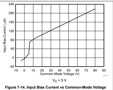
Could you please provide a graph or exact numbers for expected minimum/maximum values for the input bias current as a function of the common mode voltage?

They need a minimum and maximum input bias current, especially for common mode voltages of 32V, 9V and < 9V.
For example for Vcm = 12V, IBias = 90 µA ± x µA

Best regards

  • Hello,

    Thank you for your post. I would encourage you to take a look at figure 7-14.

    This plot is for the following conditions: Temp = 25°C, VS = 5 V, VCM = 12 V, and VREF = VS/2. 

    Will this work for them? 

    Best Regards,

    Joe

  • Joe, thanks for taking care of this question.

    My customer needs the minimum/maximum values for the input bias current. I believe the values in the datasheet and graph are typical values.

    BR

  • Hello,

    These plots are typical values. For this device, the limits are not warrantied. This plot is the most information we can provide for Ibias performance over common mode voltage for the INA240.

    I would suggest your customer take a look at the INA241A and INA241B as these devices have warrantied input bias current limits.  

    Best Regards, 

    Joe

  • Thanks Joe! I will talk to the customer and see if this is an option.

    BR

  • Thank you for your response. Currently, it is not planned to switch to the INA241, as the common-mode behavior of the INA241A2 at high frequencies (20 kHz to 100 kHz required) is not satisfactory for them. The INA240A1 has shown better behavior in the real world. They have not looked at the INA241B2 in practice yet, measurements are still pending.

    The INA240A1 has so far proven itself very well in theory as well as in practice for their application.

    They need a rough orientation with regard to min/max for the input bias current, i.e. with which tolerance they can set up their tolerance calculation. For INA241, a ± 10 µA tolerance is specified in the datasheet for Vcm = 48 V. Is that realistic for the INA240 over a common-mode voltage range of 0 V to 36 V? (The input bias current is almost constant over temperature)

    Thanks

  • Hi,

    Thank you for promoting the INA241 devices.

    I will be providing the INA240 ibias data to you on Monday of next week. Thank you for your patience :)

    Best Regards,

    Joe

  • Hello,

    I understand that they need a tolerance calculation but why is the input bias tolerance a concern to them? Are they adding extra resistance in series with the inputs for filtering? Generally, the low trace impedance of the input path is low enough to cause extremely limited measurement error as a result of ibias.

    I want to reiterate that we cannot warranty any performance outside of the datasheet and while I am providing a general rule of thumb, this is by no means a guarantee of performance.

    As a rule of thumb you can assume a ±20% in ibias typical values. 

    I hope this helps them with their design and we have no additional data that we can provide as ibias was not tested as extensively as on the INA241 devices.

    Best Regards,

    Joe 

  • Thank you Joe! I acknowledge the statement that we cannot guarantee this and have highlighted this to the customer as well.

    BR

  • FYI, this was helpful for the customer. This topic is relevant for them in an Open Connection diagnosis, as they have found that the input bias current of the INA240 has a decisive influence. 

  • Hello,

    Thank you for the clarification and I will now close this post.

    Best Regards,

    Joe