This thread has been locked.

If you have a related question, please click the "Ask a related question" button in the top right corner. The newly created question will be automatically linked to this question.

INA333-Q1: Vcm & Vdiff versus Vout (TI Tools)

Part Number: INA333-Q1
Other Parts Discussed in Thread: INA333

Hello, 

I have a design that uses the INA333 as the instrumentation amplifier and main gain stage for a relatively slow (<10Hz) but highly precise input signal. The input signal has a negative leg of constant two volts with the differential signal riding on top of that at ~10mV to ~320mV.

So at full scale range the input is roughly...

  • Vcm = 2V+320mV/2 = 2.16V
  • Vdiff = (320mV - 10mV) / 2 = 155mV

I want to interface this signal to a 5V referenced ADC and so I am using the INA333 with a nominal gain of (1+100/10) = 11.

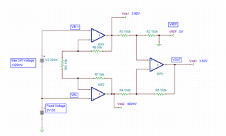
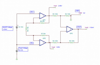
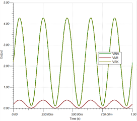
I have this simulated in TINA TI and things appear to work great...

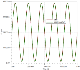
(NOTE: TINA simulation was with Vdiff,max = 390mV, a more conservative demonstration)

Input Vs Output Waveforms:
Input Vs Output/Gain Waveforms:
But just to double check that the sim isn't misleading me I've been using the TI Analog Engineer's Calculator Tool and the parameters look good...
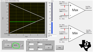
Plenty of margin for the 320mV even with quite a bit of slack on the 2V Vmin setpoint (as low as 1.75V is sufficient, going higher should just help). And for the 10mV minimum differential there also doesn't seem to be any issue.

....

But here's the kicker.

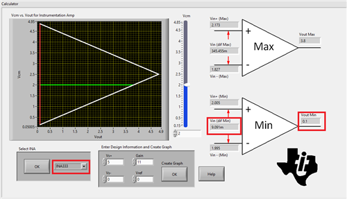
My coworker has a newer version of the TI "Analog Engineer's Calculator" installed and it shows that this design will not close and actually has negative margin... But I can't figure out why.

Output from his (newer) version of the tool:
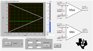
If I adjust the negative leg setpoint to be larger (say 2.5V instead of 2V) then I am able to get the maximum differential to close... but the minimum voltage is limited to 27mV no matter what common mode I use... Seemingly mapping to a hard limit Vout Min of 0.3V.

VCM = 2.5V:
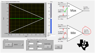
We swept the entire possible Vcm range with these Vs+/Vs-, Gain, and Ref settings and it shows a static 27mV minimum differential and a constant Vout Min of 0.3V...

So yeah, we are confused -- the datasheet for the INA333 implies that the device can swing within 50mV of the output, so I don't understand what is driving this minimum voltage of 0.3V... I also don't understand why the old version of the Analog Engineer's Calculator supported our design as having good margin (as does TINA TI simulation) while the new version shows that it is a dud.

Can someone from TI advice? Should we trust the newer version of the calculator and redesign accordingly?

This is fairly time critical (we were just about to order dev boards before we caught this and the boards and lead times are quite expensive/long)/

  • Hi Wolfhort,

    Although the datasheet specifies a 50mV output swing range above and below the rail, this specification is for an output swing slam test. This spec is for the saturation output voltage where the output stage of op-amp no longer runs in its linear operating range right at 50mV.

    A more conservative specification, to ensure the circuit operates linearly, is the output voltage should stay at least 100mV away from the supply rails. See the more conservative "gain error" and "gain nonlinearity" specifications in the datasheet, which specify Vout to 100mV from the rails for linear operation:

     Nevertheless, even using this more conservative guideline, I would expect that your circuit is still inside conservative linear range, given that all internal INA333 amplifiers are within the output swing operation, with their output showing more than 100mV above GND and below 5V-0.1V... 

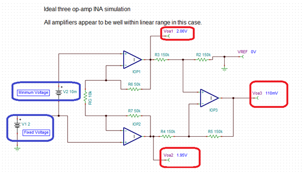
    Below is a quick simulation using 3 ideal op-amps, applying your minimum differential voltage of +10mV, where the instrumentation input negative terminal is fixed at 2V, REF=GND.  Notice, all op-amps have more than 100mV headroom from the supply rails and hence should be inside the linear region.,.  

    In short, I suspect this is an error/bug on the input/output range calculator, and your circuit is inside the permissible linear range as it is, but let me verify/get confirmation with the team, in case I am mistaken.

    Please allow me 24 hours.

    Luis

  • Hi WolfHort,

    I discussed with a couple of Engineers in the team. 

    The output swing limitation of the INA333 output stage amplifier (and internal amplifier outputs) should be limited to ~100mV from the supply rails, as shown on the post above/

    In your circuit, with the INA333 powered with V+=5V, V-= GND, RG=10K (Gain = 11V/V), REF=GND, and the INA333 output sees a relatively high-impedance load (greater than 10kΩ) 

    If your maximum differential signal is positive +320mV, with the negative input terminal at fixed 2V DC, and the IN+ at +2.320V, the INA333 is well within linear region, with all 3-internal amplifiers working within the linear region, and the output of the INA333 at +3.52V. 

    If your minimum differential signal is positive +10mV, with the negative input terminal IN- at fixed 2V DC, and the positive input IN+ at +2.010V, the INA333 is in the permissible linear region as well with the output sitting at 110mV. This meets the output headroom requirement of 100mV above GND to remain in linear range.


    The INA333 VCM vs Vout calculator limits will be updated in the next few weeks to reflect the output swing of the of the INA333 internal amplifiers is limited to 100mV from the rail supplies to remain in linear region.

    Thank you and Regards,

    Luis

  • Hi Wolfhort,

    The calculator will be updated within the next couple of weeks.  I will close this post.  Nevertheless, please feel free to post if you have further questions.

    Thank you,

    Kind Regards,

    Luis

  • Thanks ! This was very helpful follow up and gave me confidence in our solution.

  • Thank you Wolfhort!  Happy to help.

    The Analog Engineer's Calculator was just updated last Friday to reflect the output swing of the of the INA333 internal amplifiers is limited to 100mV from the rail supplies to remain in linear region. 

    Thank you and Kind Regards,

    Luis