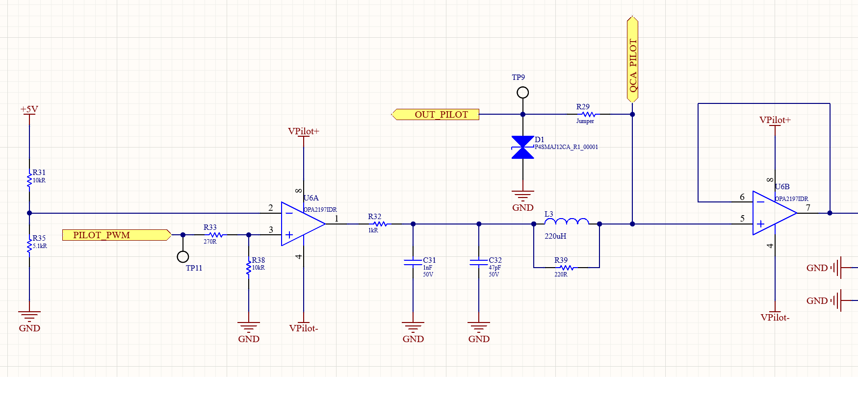
Schematic Design with OPA2197IDR
Notes:
Vpilot+: +12V
Vpilot-: -12V
The OUT PILOT line is a PLC (power line communication) line. A signal in the frequency range of 2 to 30 MHz is superimposed on this line. But these signals have no effect on the operating state of the opamps.
Hi,
The circuit above is included in the card we use in the electric vehicle charging station. These cards fail after working for an average of 1-2 months.
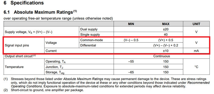
+12V is produced on the 1st pin of the 1st channel of the opamp. We also measure the voltage produced in the second channel of the opamp (from the 5th pin of U6B). The resistance value between the 5th pin and the 4th pin (Vpilot-) of the U6B component is 1k ohm (Resistance measurements were made by removing the opamp from the card).
Since the resistance value has decreased so much, the +12V voltage produced (produced by the U6A component) is measured at -10V level. But the value I should read is +12V. That's why the card goes into failure state.
My question is this; Why does the resistance of the 5th pin of the opamp decrease compared to the reference point? Thank you in advance for your support in this matter.
TC


