This thread has been locked.

If you have a related question, please click the "Ask a related question" button in the top right corner. The newly created question will be automatically linked to this question.

LM6172QML-SP: AN0009 Referenced for Slew Rate and GBW testing

Part Number: LM6172QML-SP

The datasheet for LM6172QML-SP has footnotes referencing AN0009 for the test circuit for both Slew Rate and GBW testing. I cannot seem to find that app note anywhere. Is it still available? Or are the test circuit details available from anywhere else?

Thanks!

  • Hi Tim,

    That app note does not appear to be available anymore. I am checking to see if the test circuits can be found in any other documents.

    Thanks,

    Nick

  • Thanks Nick, any luck on finding the test circuit or test conditions for these parameters?

  • Hi Tim,

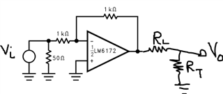
    Sorry for the delayed response. I was not able to find the application note referenced in the datasheet. The LM6172QML-SP was characterized by another team and I am working to learn more of the test specifics since these are not well outlined in the datasheet. I can share what the general test circuit would be, but I am working to get specific value for Rload as well as Rf and Rg.

    Slew Rate Test:

    This is set up so that the device is in a gain of 2V/V. The input voltage is terminated for 50 ohms. The input voltage as specified in the datasheet is 5Vpp with rise/fall times of 3ns. I am working to confirm that Rf and Rg used for the characterization were 1kohm and I believe that Rload was 1kohm for this test. Rt should be set to terminate to the equipment used to measure the output.

    GBW Test:

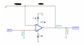
    I suspect that Rf was 1kohm for this test. Typically, GBW is characterized by setting the device in a gain of 20V/V (G = 1 + Rf/Rg) and applying a small input voltage (something like 50mVpp). Like above, I also suspect Rload was set at 1kohm. Therefore, R2 and R5 in the schematic above are placed to have an approximate load of 1kohm and terminate for 50ohm measurement equipment. From here, GBW can be found by determining the -3dB frequency of this configuration. Multiplying the -3dB frequency by 20V/V will provide the approximate GBW.

    I am still working to figure out if this is the exact test conditions that were used for the datasheet plots, but this will provide the general test circuits for measuring these specifications. 

    Thanks,

    Nick

  • Hi Nick,

    Thanks for the additional info. Rf=1k was my best guess based on one note in the datasheet about 1k being the preferred minimum, but wasn't sure about RL and wanted to be sure we're matching original test conditions as best as we can. Let me know if you are able to confirm those values.

    Thanks,

    Tim

  • Hi Tim,

    I am looking into this to confirm values and will let you know when I have an update.

    Thanks,

    Nick