This thread has been locked.

If you have a related question, please click the "Ask a related question" button in the top right corner. The newly created question will be automatically linked to this question.

INA849: I need low noise+distortion, gain 1->1000, input from the INA849

Other Parts Discussed in Thread: INA849, PCM2903, OPA211, JFE2140, JFE150, OPA145

Hi!

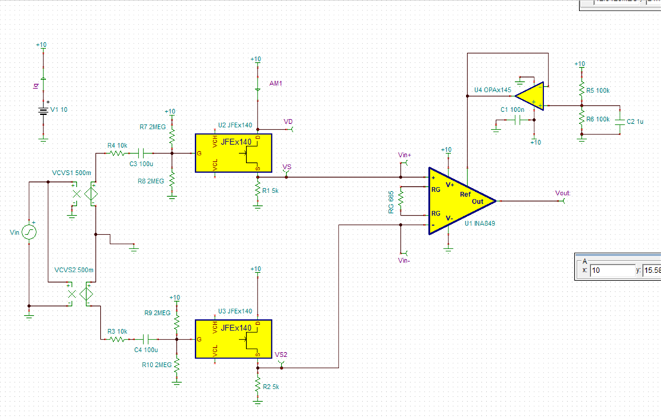
I have built an instrumentation amplifier using the INA849 chip. But my signals are VERY weak, so even though the INA849 gives me a gain around 1500, I need a second amplifier step to amplify my signal up to a 1000 times more, manually adjusted with a potentiometer. The crucial criteria is to add as little noise and distortion to the audio-like signal as possible.

The INA849 is a mono amplifier, so I don't need a stereo amplifier.

The output from the second amplifier will be send to a PCM2903 audio A/D converter.

I look forward to hear from you.

Thank you.

  • What are the supply/input/output voltage ranges?

    You probably want a low-noise amplifier like the OPA211.

  • I haven't measured the output level of the INA849, but when I feed it to the PCM2903 A/D-converter the digitized output level of the PCM2903 is displayed by my audio software as around -30 dB - which means that it can be amplified about a 1000 times more.

    The power supply will be dictated by the need for low noise and significant gain.

    For the INA849 I use two NiMH batteries of about 15V.

  • Hey Henrik, 

    You may take a look at using a high input impedance JFET front end. I have two application notes. One is for the JFE150 and the other is the JFE2140. I demonstrate how to achieve a gain of 1000 V/V in each case. This is an ultra low noise design. 

    https://www.ti.com/lit/an/slpa018/slpa018.pdf?ts=1706542334473&ref_url=https%253A%252F%252Fwww.ti.com%252Fproduct%252FJFE150

    https://www.ti.com/lit/an/sboa563/sboa563.pdf?ts=1706542475541&ref_url=https%253A%252F%252Fwww.ti.com%252Fproduct%252FJFE2140

    Best Regards, 

    Chris Featherstone

  • Thank you!

    But I am not sure if you are suggesting putting the JFET circuitry before or after the INA849? :-)

    Inserting it before the INA849 would mean having 2 JFET circuits - one in front of the V+IN and one in front of V-IN.

    In my present configuration, I have 2 Monacor pick-up coils (normally used as guitar microphones) connected to V+IN and V-IN, where one coil is placed next to my signal source and the other is only picking up the background noise, so the difference between the input to V+IN and V-IN is the wanted signal and the noise is rejected by the Common Mode Rejection.

    Note: The Monacor coils have an impedance of about 1 K Ohm at 1 KHz, and the resistance is about 280 Ohm, so the inductance is supposedly about 159 mH.

  • Hey Henrik, 

    If you need a high input impedance than the JFETs are typically the go to devices since they have low noise and high input impedance. You could use a JFE2140 (dual JFET) configured in a source follower configuration (1 per input) in front of the INA849 if you need the high input impedance. I only mentioned these if you need high input impedance and a gain boost prior to the INA849.

    If you do not need the high input impedance but need further gain after the INA849 you might take a look at the OPA211 that Clemens mentioned or possibly the OPA145. 

    Best Regards, 
    Chris Featherstone

  • OK. So I can put the JFET2140 in front of the INA849 or put the OPA211 or the OPA145 after the INA849 in order to amplify my very weak signal about a 1000 times more before it enters the PCM2903. The 'million dollar' question is which of the 2 solutions gives the cleanest signal into the PCM2903? :-)

    Do you know the answer to that question?

  • Hey Henrik, 

    What is the gain you are currently using for the INA849?

    Best Regards, 

    Chris Featherstone

  • In practice, with my current variable resistor (potentiometer), I get a gain around 1500, because I feed it to both channels on the PCM2903. Else it would be around 3000.

  • Hey Henrik, 

    Based on the provided information, I believe going into the INA849 in a gain of 1000 or 60 dB and then gaining up even further after using a low noise amp would be sufficient. I have simulations to demonstrate when you will benefit using the JFET front end. I used the JFE2140 in a source follower configuration to replace the front end of the INA849 and varied the source impedance such that we can observe the noise performance between the JFET front end vs going directly into the INA849. Please note that this was for a different design and my gain here is 20 dB and therefore you may repeat this analysis for 60 dB. However the INA849 noise gets better with higher gain so this is a conservative analysis and demonstrates that even with 20 dB gain and a source impedance of 1k you would still be ok going directly into the INA849. I have attached the tina simulation below. 

    Below you can see that you would benefit using the JFET front end when the source impedance is 10k or greater. With a source impedance of 1k and below they are nearly the same. 

    INA849 with JFE Front End With mic source impedance.TSC

    Best Regards, 

    Chris Featherstone

  • Thank you for your reply!

    If I understand you correctly, you are recommending that I put the JFETs in front of the INA849 to achieve the extra gain I need?

    Are VCVS1 and VCVS2 in your diagram symbolizing my 2 Monacor pick-up coils?

  • Hey Henrik, 

    The JFETs are in a source follower configuration and in a gain of 1. The only reason to use them in this configuration is if you need a high input impedance such that your sensor does not get loaded down by Ib. If your application is not sensitive to the input impedance of the INA849 (bipolar input lower impedance) then you would not need the JFETs. In which case you can simply use the INA849 in a gain of 1000 and if you need further gain this could be achieved by adding another gain stage using a low noise amplifier. I have not modeled your pick up coils. You may replace the front end in the simulation attached in order to simulate with the model of your coils. 

    Best Regards, 

    Chris Featherstone

  • This is the Input impedance of the INA849, according to page 5 in the documentation:

    Z in = 1 GΩ + 7 pF

    Why would I need a source follower circuit between my coils and that?

  • Henrik, 

    If you have a high source impedance that cannot deliver the input bias current to the part then you would want to choose a high input impedance front end. Bipolar inputs such as the INA849 have very low voltage noise performance but have higher input bias currents than JFET inputs. The JFET gives you the high input impedance and you still get great noise performance. 

    Best Regards, 

    Chris Featherstone

  • My pick-up coils have impedance = 1 kOhm, and you yourself wrote about the noise analysis:

    "With a source impedance of 1k and below they are nearly the same."

    So I don't really understand why I should bother implementing a JFET front end?

    To me, it seems more important choosing the right (low noise, low distortion) amplifier for the 30 dB amplification AFTER the INA849.

    The OPA211 seems like a good candidate, but the TI product range is vast and complex, so I cannot really see if there are even better choices?

  • Hey Henrik, 

    The information regarding the JFETs is only provided as an option if you need it based on your design and sensor. It appears based on the provided information that you may pass on that idea and use an additional amplifier after the INA849 instead. 

    On our webpage we have our featured audio devices that show the architectures and noise. This may be a good starting point for you to analyze the parameter tradeoffs and key care abouts in your design. Additionally you can view all the audio devices and filter down to the key parameters of interest. The tradeoffs between the devices such as Iq, noise etc is much easier to narrow down using the filter scheme. This will help narrow down the search for the best fit. 

    https://www.ti.com/amplifier-circuit/op-amps/audio/overview.html

    Best Regards, 

    Chris Featherstone

  • Thank you!

    1. I will research the audio amplifiers.

    2. I want to apologies for being so rejective to your kind suggestions about having a JFET front end to my INA849. I must have had a momentary lapse of reason... forgetting that the impedance of the coil is proportional to the frequency. So at 10 KHz it will probably be around 10 KOhm, which makes the JFET front end relevant.

  • Why are JFE150 and JFE2140 on that audio op amp overview page, when they are not on the list you get from the "View all products" button there?

  • Hey Henrik, 

    Why are JFE150 and JFE2140 on that audio op amp overview page, when they are not on the list you get from the "View all products" button there?

    I was wondering the same thing yesterday. I will have to run that by our marketing team. 

    Best Regards, 

    Chris Featherstone

  • I have chosen, and ordered, the OPA211 op amp, for it's low noise and distortion, as the second stage amplifier, after the INA849 instrumentation amplifier, and before digitizing the signal in the PCM2903 ADC, which sends the signal via USB to my audio software. 

    1. The question is how to implement the variable gain, without adding too much noise or distortion?

    My immediate plan is to implement the variable gain somewhat like this:

    www.circuitlab.com/.../

    In that circuit, I presume Gain = (R2 + R4) / R1, where R4 is the potentiometer.

    2. But what is the optimal size of the resistors R1 and R2, in terms of ohm?

    In the circuit I link to above, R1 = R2 = 100 ohm. Is that somewhat arbitrary? Would a higher or lower value give less noise and distortion?

    3. And are there specific resistor and potentiometer technologies that give less noise and distortion?

    4. I need around 30 dB amplification, according to Audacity audio software. But when Audacity says the signal is -30 dB, does that mean that I need gain = 1000 [V/V] or is that a misunderstanding of the dB scale?

    I look forward to hear from you. Thank you. :-)

  • Hey Henrik, 

    3. And are there specific resistor and potentiometer technologies that give less noise and distortion?

    When you design using a potentiometer it is a good idea to use AC coupling especially when designing with bipolar input stages such as the OPA211. Having DC potentials across the potentiometer and also high bias currents flowing through the potentiometer you will end up with crackling noises as the wiper is adjusted. The AC coupling will use a capacitor in which case you want to make sure that your charge up times when the circuit is powered up are long enough to fully bias up the circuit. If audio is present during this charge up time distortion will occur as the capacitor charges up. So the initial startup time should be accounted for if you would like to minimize this startup distortion. 

    2. But what is the optimal size of the resistors R1 and R2, in terms of ohm?

    In the circuit I link to above, R1 = R2 = 100 ohm. Is that somewhat arbitrary? Would a higher or lower value give less noise and distortion?

    The smaller the resistor value the lower noise contribution from the resistor however there is a trade off of power consumption with lower resistor values depending on how they are configured in circuit. The optimal resistor value will depend on the design goal noise tolerance. Since this stage comes after the INA849 you will have a pre gain with the INA849 to help with the signal to noise ratio in which case you most likely will be able to tolerate higher value resistors. 

    For a detailed discussion on noise and low distortion design we have a series on both that can be found here:

    https://www.ti.com/video/series/precision-labs/ti-precision-labs-op-amps.html

    I will add to the discussion further tomorrow on the other inquiries. 

    Best Regards, 

    Chris Featherstone