This thread has been locked.

If you have a related question, please click the "Ask a related question" button in the top right corner. The newly created question will be automatically linked to this question.

LM358A: PIR conditioning circuit

Part Number: LM358A
Other Parts Discussed in Thread: LPV802

emma_bode.TSCemma_lpv802.TSC

Hi, 

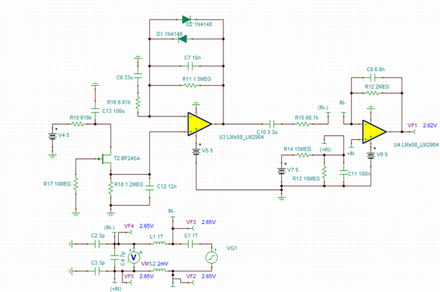
I have built a PIR AFE circuit closely based on this reference design. 

The differences are as follows:

- using LM358AMX/NOPB (dual amp in SOIC package)

- reduced second stage gain to meet input requirements for ADC circuit used in leiu of comparators 

- Vs = 5V

- Using LHI 958 PIR sensor 

For the most part, the design behaves as expected, but occasionally I'm noticing it begins to oscillate (sometimes due to SMT issues) so I believe it's unstable. 

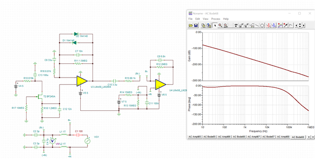
I've attached 3 simulations done based on this e2e post which yielded the following results: 

Simulation A: Original circuit with LM358AMX/NOPB - not good 

Simulation B: Change PIR bias resistor to 47k with LM358AMX/NOPB - phase margin = 32deg, unstable 

Simulation C: Original circuit replacing opamp with LPV802 - stable with 52 deg phase margin: 
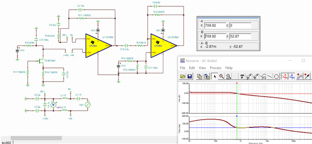
Can you help me understand which specific opamp parameters are causing these different behaviors? If I need to switch to a different amp, is there one that is footprint compatible you would recommend?

Best,

Emma

  • Emma,

    Be sure to check the DC value of the input. This may be the reason that "A" doesn't have any gain.

    Op amps with high bandwidth have loop gain at frequencies where capacitors have low reactive resistance so extra care is need to counter act the effect of this. Try adding 6.8k in series with C7, so high frequency loop gain is 1/2 (where phase should be better)

  • Hi Ron, 

    Thanks for your suggestion. I realized I had an error in my sim (In+ connected to wrong side of the JFET), once I corrected this I was able to get an output even with the 1.2M pulldown. 

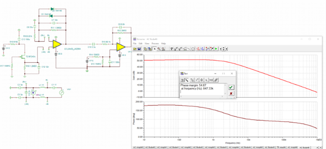
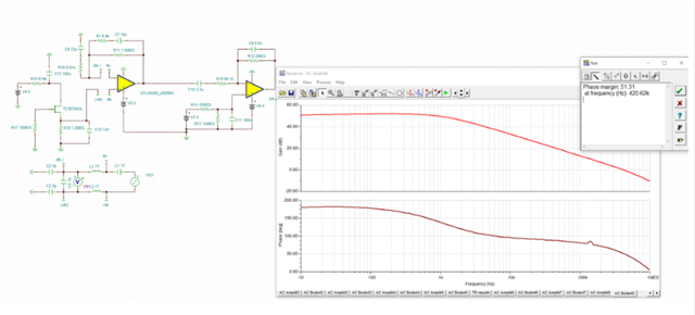
    I also added in D1/D2 clamping diodes which I do have in my circuit and were recommended by a couple of app notes /ref designs to prevent saturating the opamp. Adding these diodes actually gave me > 45 deg phase margin alone, as did adding the 6.8k series resistor you recommended (have added photos below, sorry they are quite blurry). 

    My next question is how would you recommend I test stability in-circuit, without a bode analyzer? 

    I tried to simulate the load step method from the Precision Labs (using 45uV input - calculated based on 10mV/(220V/V gain of my first stage), but not really getting a viable output. I'm thinking this may be because this is a bandpass filter circuit, I may need to use a different method? 

    Diodes only (representative of my existing circuit) 

    With series resistor 

    Thanks, 

    Emma

  • Hi Ron, 

    One more question: I tried adding an output capacitor to the circuit at the output of the second op amp (the input is to an ADC, so there should not be significant capacitor loading, just wanted to test it out) and didn't see any change to the bode plot even with a 100uF cap. Is there something I'm missing in my sim? 

  • Emma,

    Try a load transient on a real circuit. You can use a voltage pulse generator with a series resistor to get a load current transient. 

    The simulation phase gain taps are setup for 1st op amp loop. The load cap on the 2nd op amp is not part of that closed loop.  

  • Hi Ron - got it, here we go with more questions.... 

    (1) You mean actually loading the output rather than testing with an input step at the non-inverting input?  Do you have a recommendation on the level for load current and slew rate? The precision labs vids recommend a step input, scaled down based on system gain. In my case this value is very small (10s of uV) since the gain is large.

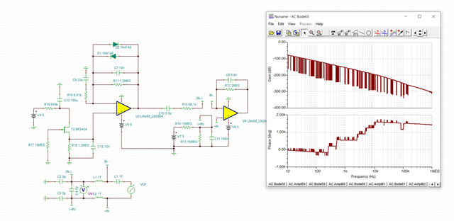
    (2) Measuring now the second stage, I am getting a strange output again. DC node voltages seem ok? 

    Thanks

    Emma

  • Emma,

    1) Yes, inject at output pin. 1mA current step (fastest edge) should be ok. 

    2) For noisy bode sims try reducing C1 to 100F

  • (1) Still not seeing positive gain when reducing C1 => 100F 

    (2) When loading the output should I again break the circuit across the input +/- and measure the response there? 

  • 1) C8 R12 needs to connect to (IN-) instead.

    2) no breaks, just load output and observe output.