This thread has been locked.

If you have a related question, please click the "Ask a related question" button in the top right corner. The newly created question will be automatically linked to this question.

LMP7721: Clarifications on Input Protection

Part Number: LMP7721
Other Parts Discussed in Thread: TINA-TI

Hello, 

Was hoping to ask for some clarifications to section 7.3.7  Input Protection of the LMP7721 datasheet (p. 17). Specifically having troubles with comprehending the significance of the sentence "These diodes can conduct current when the input signal has a really fast edge, and, if necessary, should be isolated (using a resistor or a current follower) in such cases.". Does this entail that if the signal I am inputting into the -IN pin is a square wave (leaving +IN to ground), would I expect more current leakage and therefore noise to be generated from the LMP7721?

For context, I am modulating a photodiode to generate a square wave (blinking an LED over the photodiode). 

Thank you for taking the time to read my inquiry.

Link to datasheet below:

 https://www.ti.com/lit/ds/symlink/lmp7721.pdf?ts=1706603911969&ref_url=https%253A%252F%252Fnl.mouser.com%252F

lmp7721.pdf

  • Hi Camille,

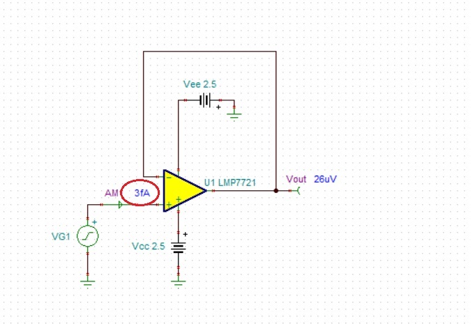
    The LMP7721 typical input bias current is 3fA (see below) but this is under steady-state (DC) conditions).

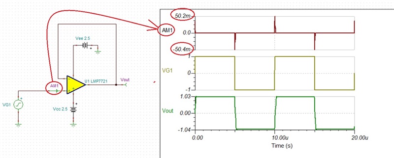
    The Input Protection section refers to what happens when a fast-edge input signal is applied to the input.  Since no op amp can react infinitely fast, a fast large signal (like +/-1V shown below) will result in forward biasing back-to-back protection diodes resulting in high input current (+/-50mA) that may damage the diodes.

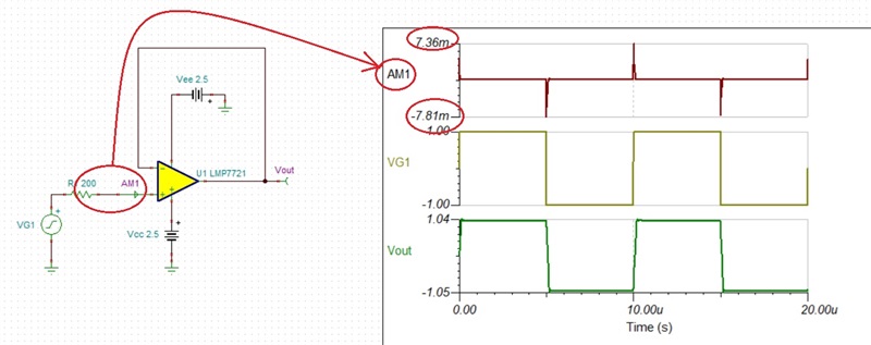
    Since most of the internal protection diodes are rated for maximum +/-10mA input current, this requires adding a series input resistor, R1,  to limit the input current below 10mA.

    R1 = [(1V-(-1V)]/10mA = 2V/10mA=200ohm. Adding 200ohm input resistor lower the max input current from +/-50mA down to +/-7mA - see below.

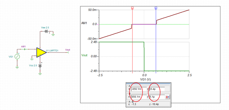
    The same applies to LMP7721 use as a comparator where taking the inputs more than 650mV apart will result in high input current and for this reason should not be use in such application - see below.

    LMP7721 transient input current.TSC

  • Thank you, Marek

    I appreciate the thoroughness and effort that you put in your reply! That was vey insightful :)

    Just want to confirm if you used LTSpice for the circuit simulations shown?

    I have a related question that builds upon your answer with regards to using a modulated current source rather than a modulated voltage source (as you showed). I am not 100% sure what the question etiquette is for this forum, should I make a new post for my additional queries? Or simply continue asking in this thread?

    Please let me know. 

  • Camille,

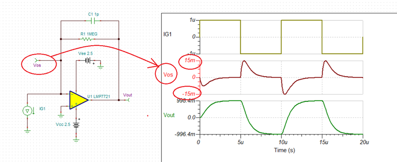
    You may use the same forum for follow up questions here.  Using LMP7721 for TIA application typically does not result in a large differential voltage between the input terminals and thus you do not need to worry about turning on back-to-back input protection diodes - see below (Vos = +/-15mV).

    I used for my simulation Tina-TI (see schematic below).  You can download a free version by clicking on following link: https://www.ti.com/tool/TINA-TI

    LMP7721 transient TIA.TSC

  • Hi Marek,

    Thank you for the clarification! I see that for the case of the TIA, the modulated voltage supplied to the input terminal -IN is Vos (product of IG1 and the feedback system), and since that voltage is expected to be well below +/- 1V (like VG1 in your previous example) the input current will be << 10 mA. No need to compensate the protection diodes with the resistor in series to the op amp input. 

    I really appreciate you sharing the software and file used for your circuit simulations. I will use the file to simulate the TIA with realistic IG1 values I expect from my modulated photodiode.

    Cheers

  • Sounds good and good luck with your design!