This thread has been locked.

If you have a related question, please click the "Ask a related question" button in the top right corner. The newly created question will be automatically linked to this question.

INA188: Data sheet spec of interest

Part Number: INA188

If the gain of an input signal puts the output level near or above ~1.5V, the output is no longer linear as a function of GAIN..

Question: What item on the data sheet defines the limit that I am seeing.INA188.pdf

Please see a typical bread-boarded circuit example.

  • Hey Randall, 

    What is your common mode voltage set to?

    We have a free to download Analog Engineers Calculator (link below) that can help assist in finding the input and output ranges and linear operating range. This can be used in parallel with Tina Ti to check the functionality. Tina is also a free to download Spice simulator that I have linked below. 

    https://www.ti.com/tool/ANALOG-ENGINEER-CALC

    https://www.ti.com/tool/TINA-TI

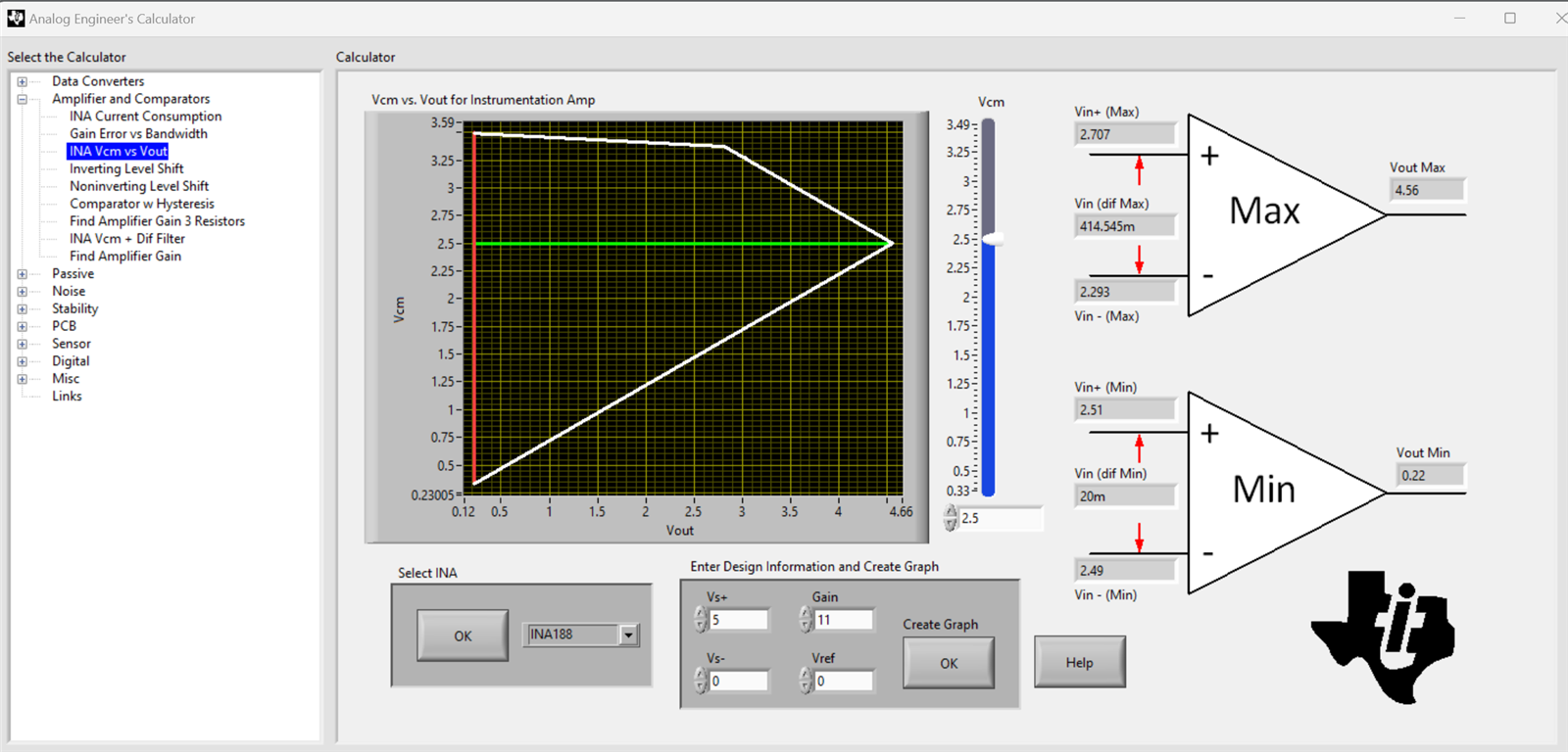
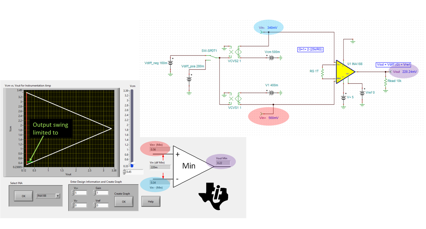
    With the reference tied to ground on a single supply you can see that the area of linearity is limited to inside the plot below. 

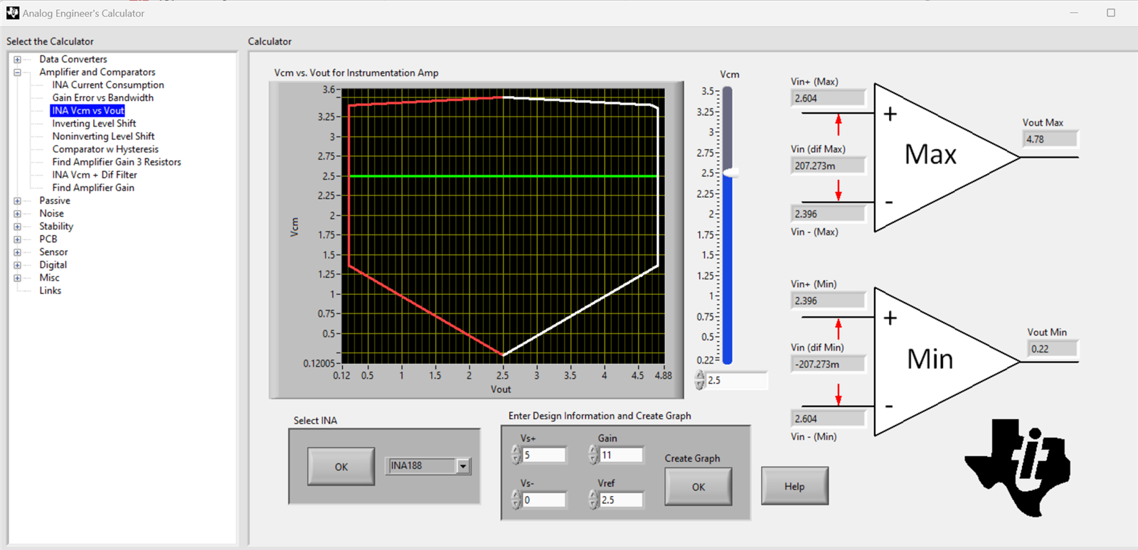
    By changing the reference voltage to mid supply I was able to adjust the linear range as shown below. 

    Best Regards, 

    Chris Featherstone

  • Hello Chris,

    Yes the simulator tool works and I can see the effect on the bias level on the bench too. ( 5V supply, Vref at gnd.)

    What I don't see however is where on the data sheet for the INA188 I am outside the operating parameters.

    For instance, if my input Vcm is .45V (V-in=.5V, V+in=.4V) and V-in is less than 1V at this input I am in a nonlinear mode for outputs >.5V?

    If V-in is >=1V, I am in extended linear mode range for the output.

    How does the bottom side input voltage level affect the output if we are within the Vcm spec range of 0.1V-3.5V.

    Thanks,

    Randy

  • Hey Randall, 

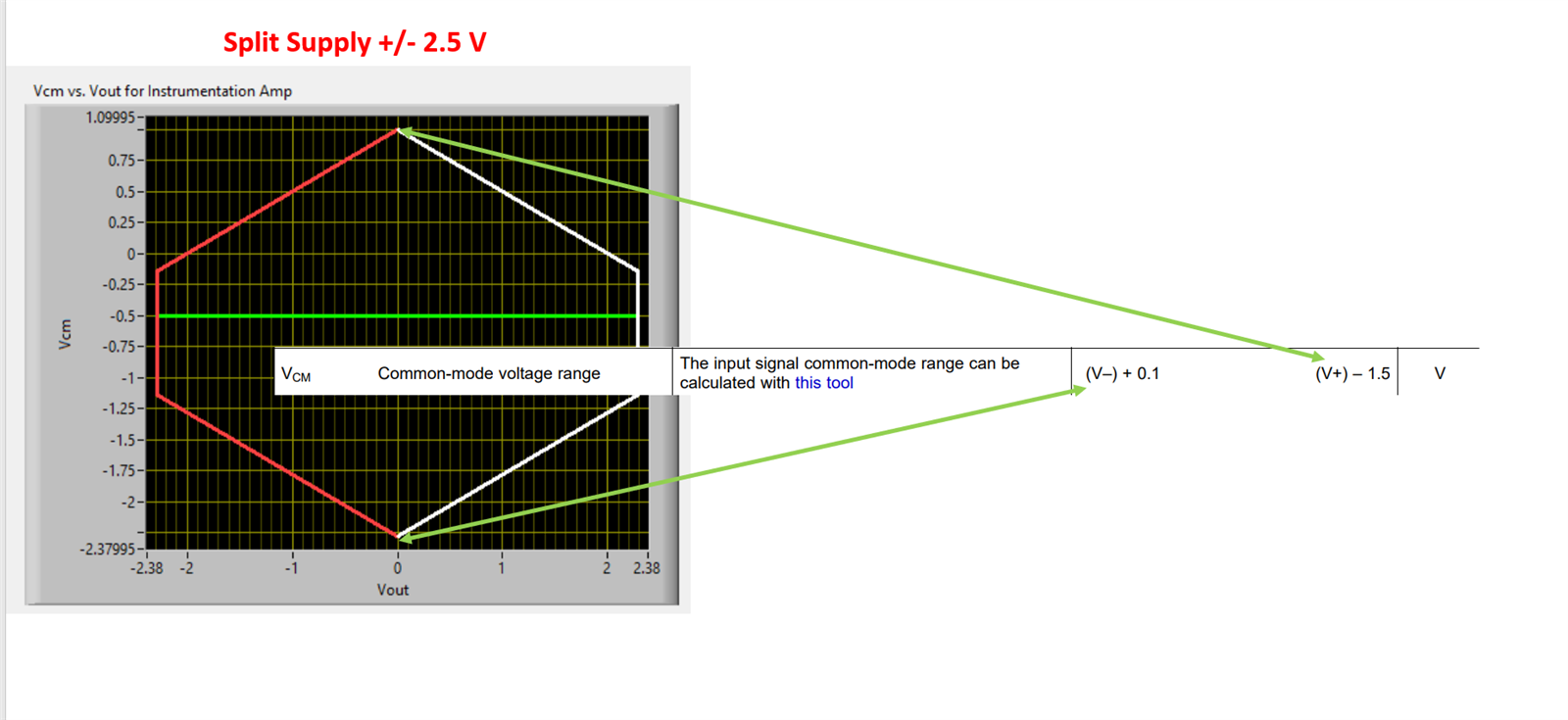
    It is a bit challenging to use the information only from the datasheet to understand the limitations. The datasheet is limited to a set of measurement conditions and as the conditions change such as the supply (split vs single), reference voltage, and gain the calculator and simulation are good guides since the INA devices are a bit complex. Below I am showing the extremes of the common mode voltage range listed in the datasheet and the calculator visual to show the limited output voltage swing at these extreme points. As the common mode voltage is adjusted up and down and gets closer to the supply rails, the linear output swing will reduce. 

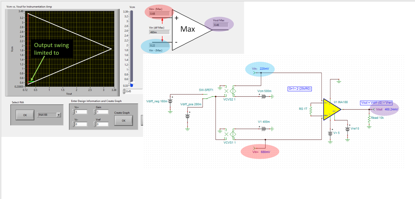
    I have simulated your conditions described and have color coded the input and output ranges between the calculator and the Tina model. 

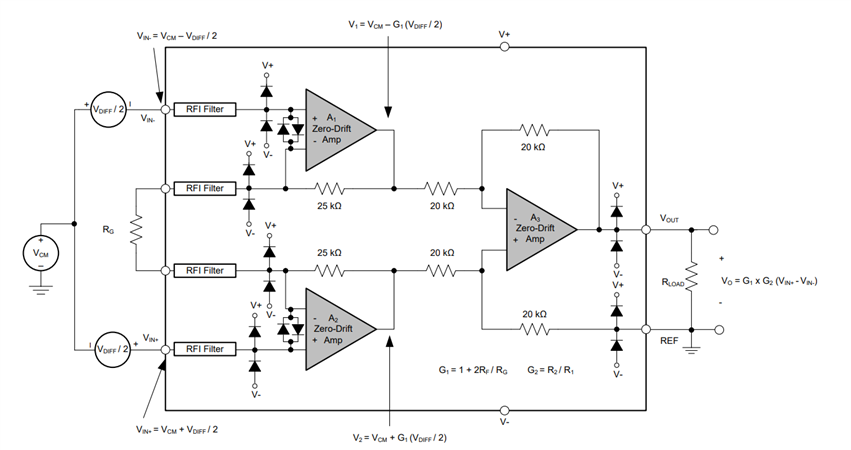
    Internally there is limitations on the input and output of each the 3 amplifiers. 

    I have attached my Tina simulation below. 

    INA188.TSC

    I hope this information helps assist in your application. 

    Best Regards, 

    Chris Featherstone