This thread has been locked.

If you have a related question, please click the "Ask a related question" button in the top right corner. The newly created question will be automatically linked to this question.

How to achieve 150M or 200M bandwidth with OPA847?

Other Parts Discussed in Thread: OPA847, TINA-TI, OPA846

Dear All,

I am developing a homodyne detector (HD) based on the OPA847 for very small signal originating from the difference current of two photodiodes (Hamamatsu S3883, 300MHz frequency response).  The circuit design is shown below.  The frequency of the laser signal I need to detect is 76MHZ. To detect such signal, the HD should offer at least 152MHZ frequency response.

However, according to my test results, the bandwidth of my HD is only about 50MHz.

How to achieve 150M or 200M bandwidth with OPA847?  Is there some problem with my circuit design?

Any help on this topic would be highly appreciated!
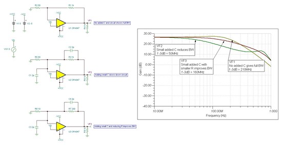
The circuit design


  • Bob,

    The problem may be parasitic capacitance in conjunction with resistors slowing down the circuit.

    The RC time constant in the signal chain and feedback loop effects the BW.

    I insert diagrams below of 3 OPA847 op amp circuits all in non-inverting gain = +20 V/V.

    Top circuit has resistor values you show with no added capacitance and give full expected BW f-3dB = 210MHz

    Middle circuit has resistor values you show with 2pF added capacitance at inverting input and across feedback R. The result is BW is reduced to f-3dB = 50MHz, same as you mention.

    Bottom circuit has resistor values change to 5x lower and with 2pF added capacitance at inverting input and across feedback R. The result is BW is improved to f-3dB = 160MHz.

    For best BW performance, RC time constants need to be minimized.

    To minimize C: remove ground and power planes from under the inverting input node, output node and feedback resistor, and traces should be as short as possible.

    To minimize R: the gain setting resistors should be kept as low as possible.

    The OPA847 data sheet shows BW over 200MHz should be achievable in gain of +20V/V with RF=750 ohm and RG=39.2 ohm.

     I also attach Tina file you can simulate.

    7571.opa847_G=20 + Cparasitic.TSC

    Tina-TI is a free download available at  http://www.ti.com/tool/tina-ti 


  • Dear  Jim,

    Thank you so much for your detailed simulation and valued advices! Your reply is so helpful to me! The Tina-TI software is also very useful!

     I have two additional questions.

     1. A small Gain, for example, 10V/V is also acceptable in my circuit. But in the case of G<12V/V, the OPA847 has self-oscillation. I met this problem before and it was post at  http://e2e.ti.com/support/amplifiers/high_speed_amplifiers/f/10/t/74579.aspx

    Before I only pay attention to the stability of OPA847, so I used a Gain of 20V/V. Until recently I was aware of that a wide bandwidth of more than 150MHZ was also very important.

    My question is, if I use G= 10V/V, how can I avoid the self-oscillation?


    2.  As shown in your attached file, when the resistor values change to 5x lower, the BW can be improved to f-3dB = 160MHz. In my real circuit, I can also use such values of resistors (Rf=200, Rl=10), as shown in the figure below.

    But are there some problems with such low-value resisters?  For example, the impedance matching, etc.

     Again, thanks a lot for your help!


  • Bob,

    #1. I think answer to G= 10V/V is in post at  http://e2e.ti.com/support/amplifiers/high_speed_amplifiers/f/10/t/74579.aspx

    Easiest solution is to use OPA846 for G= 10V/V.

    #2.  No problems for the impedance matching. The main problem is distortion worse because feedback path loads the amplifier; see data sheet plots of "HARMONIC DISTORTION vs LOAD RESISTANCE" at top of page 5. The 200/10 resistors will move the device from far right side of plots to around 200 ohms. If this performance is not enough, you may have to spin the board to remove GND/Power planes and reduce parasitic capacitance.

    Jim Karki

    HS Amps

  • Dear Jim,


    Thank you very much for your reply!

    Your explanation is very helpful to me!

    Next I will revise and test the detector . I will show my tested results after I finished it.


    Best regards,

    Bob