Hello:
I'm trying to design OPA380 for my optics lab,but have some problems。
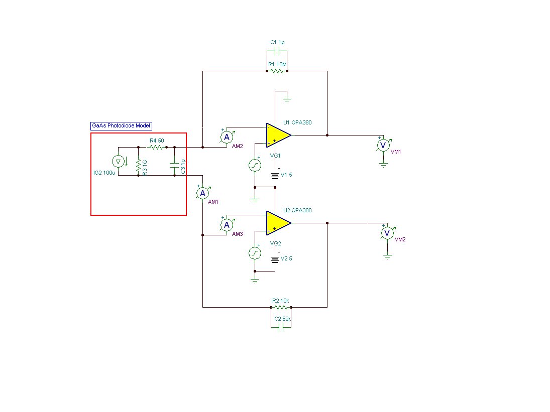
The "IN-" How to Provide the PD current path,when the OPA380 work in overdrive(Vin*G =>Vs).
OPA380 can Work in this state for long time safly?
Thanks
This thread has been locked.
If you have a related question, please click the "Ask a related question" button in the top right corner. The newly created question will be automatically linked to this question.
Yong Fan,
When a transimpedance photodiode amp output reaches its maximum output voltage, the photodiode will transition to forward biased photovoltaic operation. The diode voltage will be self-limited and no damage will occur. In any case, the OPA380 can tolerate voltages beyond the power supply rails with currents up to 10mA--see the absolute maximum ratings table.
Regards, Bruce

For this design,we have already complete experimentation.It can worked well.But we can't understanding the U1_IN- how to Provide the PD current path,when the PD current from 10uA to 1mA.In this case the U1 work in overdrive and U2 can works well.
Thanks
Yong Fan,
Thank you for providing a schematic. I understand your question now.
One possible solution is to connect a 4.1V zener diode in parallel with R1. This will cause the feedback of U1 to go to a low impedance as it approaches its full output voltage. While I believe this concept could work, the leakage of the zener diode may affect accuracy of the transfer function at low diode currents. It may be possible to locate a zener diode with very low leakage below its breakdown voltage.
Regards, Bruce.
Yong Fan,
Sorry but I forgot that U1 is biased above ground, probably at 2.5V, so a 4.1V zener diode voltage will be too high. Lower voltage zener diodes are sure to have too much leakage so I don't believe this solution will work.
Another possible solution is to connect an analog switch in parallel with R1. The logic control on the switch would be driven by a comparator which would close the switch when the output voltage of U1 approaches 4.7 volts.
The purpose of your circuit appears to be to measure the photodiode current over a wide dynamic range. You may want to consider a logarithmic amplifier for this purpose. For example, the LOG114 can measure photodiode current over an eight decade dynamic range.
Regards, Bruce.
Hi,Bruce
"Input terminals are diode clamped to the power-supply rails. Input signals that can swing more than 0.5V beyond the supply rails should be current limited to 10mA or less."(Page2 of the OPA380 datasheet.)
Did the diode Provide the PD current path?Why the demo board can works well?
Thanks
Yong Fan,
The internal diode clamp diodes protect the amplifier from damage but they do not assure that zero voltage is maintained across the photodiode. The zener diode or analog switch in parallel with R1 provides feedback to assure that zero volts is maintained across the photodiode.
Please provide the exact circuit of the demo board that you are using.
Regards, Bruce.
Yong,
I will try to explain the issue with the circuit shown in your schematic. I will assume that VG1 and VG2 are both 2.5V. Therefore, the voltage on both the anode and cathode of the photodiode will be 2.5V.
The transimpedance gain of U1 is much higher than U2. When the photodiode current increases to approximately 200nA, the output of U1 will reach its positive output voltage limit of approximately 4.8V. At this point, additional photodiode current can no longer be supplied through R1. The voltage on the cathode of the photodiode will decrease while the voltage on the anode remains constant. This will forward bias the photodiode and significantly change its characteristics.
The circuit approach I described using an analog switch and comparator will avoid this problem.
Regards
Bruce
i'm sorry i forget that the VG1=2.5v VG2=1.5v.They fix Reverse bias of the photodiode.
Theoretical analysis, if the photodiode current increases ,The voltage on the cathode of the photodiode will decrease. when it decrease to 1.5V the photodiode will stop working.
Actually ,the voltage on the cathode of the photodiode will decrease,but will not decrease to 1.25V.Just dropped to about 2.0V.This moment the photodiode will works well,it looks like, additional photodiode current is supplied through U1_IN-.
Thanks