This thread has been locked.

If you have a related question, please click the "Ask a related question" button in the top right corner. The newly created question will be automatically linked to this question.

AMC1350: Bandwidth and unused output questions

Part Number: AMC1350

Hi,

I'm looking for an isolation amplifier for a 2Vpp 250KHz signal which appears to be challenging to find. The closest I could find is the AMC1350 and I have the following questions:

1) The frequency of interest in my application is 250KHz and the BW of the AMC1350 is 275KHz up to 300KHz, will this be sufficient? I understand that AMC1350 introduces 0.4 attenuation which is not a problem to me. If not, are they any other more suited options?

2) Only a single-ended output from the opamp is needed, how to terminate the unused output?

Thanks!

  • Hi Mohammad,

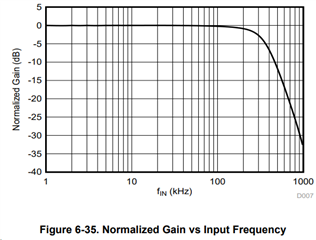
    1. If you understand there will be attenuation and that is not a problem in your application, the AMC1350 should suffice. At 250kHz there will be some attenuation, and on a square wave there are points on the signal that will exceed bandwidth. I included the graph below that shows gain versus input frequency for this part.

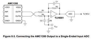
    2. Please see section 8.2.2.2 Differential to Single-Ended Output Conversion in the data sheet to see our example. 

    Best regards,

    Eva

  • Hi Eva, thank you for your prompt response.

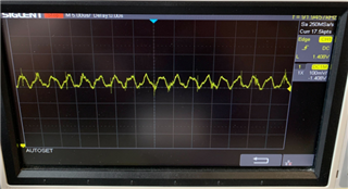
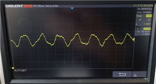
    1. The analog input is basically sinusoidal and no problem in having attenuation. I'm mainly concerned about distortion in the signal as when I tested with a 1Vpp sine-wave from a function generator connected to the AMC1350 evaluation module, I got what looked like a distorted output shown in the attached image below. There could be a measurement error that I'm not aware of. Please let me know your thoughts on this waveform.


    2. Can I simply leave the OUTN floating as it'll be very challenging to add an extra stage in the available board space? Any downsides to this?

  • Hi Mohammad,

    1. There does seem to be distortion on the output. What does your setup look like? Please let me know as that could help me consider where the distortion is coming from. 

    2. Instead of adding an extra stage you could connect your negative output to ground through a 10k resistor. This would allow for direct connection to a single-ended device, but there is no filtering or matching of the full-scale range.

    Best regards,

    Eva

  • Thanks again Eva!

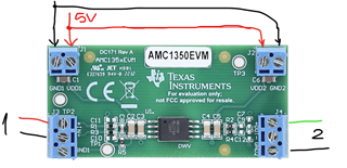
    1. Please see image. The input (1) is 250KHz 1Vpp from the function generator with load configuration set to HiZ. Output (2) is going to the oscilloscope. The 5V/GND comes from a power profiler kit and are common to both sides for the sake of this test only, but eventually they will be completely isolated (VDD1 to 3.3V and VDD2 to 5V).


    2. Glad to know it works with a pull down resistor!

    3. Sorry for adding an extra point and thanks for bringing up filtering. I currently don't have any RC filtering on the input or the output of the AMC1350 in my application circuit. The input is coming from a preamp stage and the output is going to an off-board ADC board that has its own filtering. Are these a necessary addition? If yes, what values do you think suit my application?

    Many thanks for your valuable responses and patience!

  • Hi Mohammad,

    1. Typically, the high-side power supply (VDD1) for the AMC1350 is generated from the low-side supply (VDD2) by an isolated DC/DC converter. So, there shouldn't be an issue with this in an application. The EVM should be able to share the power supply too. 

    2. Happy this helped!

    3. If the input looks clean from the preamp stage without any filtering, I think this is okay. Considering your output looks distorted, I would recommend adding filtering on the output to see if this helps. Or you could measure the output after the ADC filtering. 

    Please let me know if you can measure the input and output again after implementing these changes and if you still see distortion.

    Best regards,

    Eva

  • Hello Eva,

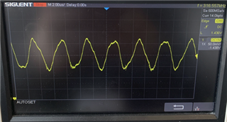
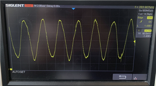
    1. In my end application I have VDD1 connected to 3.3V from one supply, and VDD2 connected to 5V from another isolated DC/DC converter. Do you see any issues with such connection? I've tested separated supplies on the EVM but the waveform still looks distorted as shown below. Also tried adding a 10K load between the scope's probe but it's still distorted. What else do you think causes this issue? (please note that these measurements are on the EVM, so it comes with some preinstalled input filters)

    The below waveform is with the function generator's output set to 50-Ohms instead of HiZ:

    And this one with the function generator's output set to 2Vpp 50-Ohms instead of 1Vpp:

    2,3. Thank you for resolving these!

  • Hi Mohammad,

    The EVM comes with 0Ohm resistors, and the capacitors are not populated so there shouldn't be filtering on the input or output. 

    Could you probe your input so I can see that as well please? I will look into this more in our lab too and get back to you.

    Best regards,

    Eva

  • Hi Eva, 

    Ok thank you for clarifying the filtering on the EVM.

    For the input, we use the Siglent SDG1032X function generator which outputs a pretty clean sine-wave.

  • Hi Mohammad,

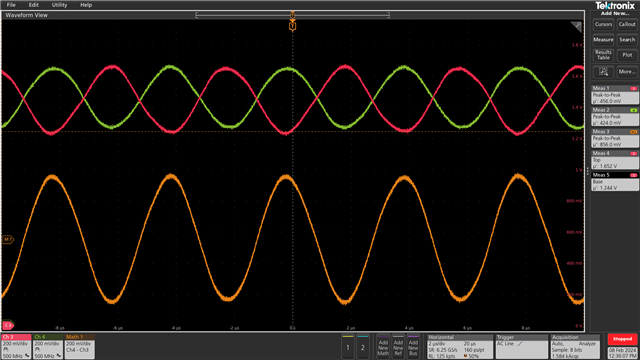
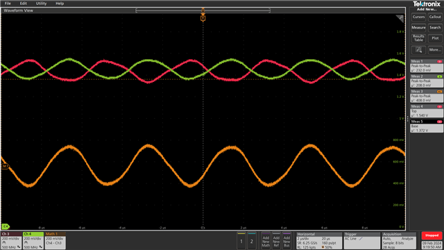
    I went to the lab and applied a 250kHz, 2Vpp sine wave on the AMC1350EVM. Green is the positive channel and red is negative. This is what I got:

    Could you please send me a picture of your input probed with your output waveform? This seems like the distortion could come from the setup so I would need more information to find the error source. 

    Best regards,

    Eva

  • Hi Eva, I really appreciate your commitment to help us, thank you. I'll be making the measurement you requested tomorrow and will share the results. That being said, it's very reassuring that we can get such a clean output at 250KHz. If I may ask, what does the output look like with a 1Vpp input signal? Because in our case the distortion was more serious at 1Vpp. I'll get back to you tomorrow!

  • Hi Mohammad,

    Sure, here is the output at 1Vpp - it still looks pretty clean.

    Thank you for working on getting those measurements! 

    Best regards,

    Eva

  • Thank you so much Eva for all your support. I consider this an answer to our last question and I'm marking this as resolved. Thanks again!