This thread has been locked.

If you have a related question, please click the "Ask a related question" button in the top right corner. The newly created question will be automatically linked to this question.

LF398-N: LF398N-NOPB

Part Number: LF398-N
Other Parts Discussed in Thread: OPA192

Hi Team,

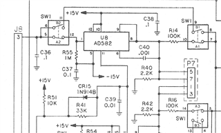
      In our existing Design AD582KD (Sample and Hold amplifier) is used. With TI suggestion, In new design we are using LF398-n. During Bench level testing we noted that, In hold mode Voltage decreases till -13.8V from 0 V. But in AD582KD IC Voltage increases to +13V. I have attached both circuit design. Is it acceptable? Why it is increasing, If IC in sample mode means it should be in constant voltage right? Please provide the reason.

Regards,

Pradeepraj M
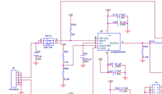
  • *If IC in Hold mode means it should be in constant voltage right? Please provide the reason.

  • Hi Pradeepraj.

    *If IC in Hold mode means it should be in constant voltage right?

    Yes, this is correct. I do not have all the details about the sample and hold circuit event. What is the voltage that you want to be held? How long is the capacitor's holding time? Please offer us additional information if the following suggestions do not solve the issues. 

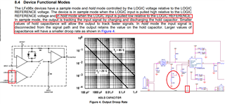
    Based on the schematic, I do not know if the circuit is toggle the Logic w.r.t. Logic Reference pin correctly. Also please check the type of hold capacitor, you will have the best holding results (minimum droop voltage), if the capacitor type is C0G, polypropylene or polyethylene. Please also make sure that the PCB is gone through ultrasonic cleaning process. 

    If you have other questions, please let me know. 

    Best,

    Raymond

  • Hi Raymond,

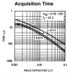
    To sample the IC we are giving 15V in logic input and for Hold mode, 0V in Logic input. We are using 0.001uf (C322C102K2R5TA7301)  X7R ceramic capacitor as holding capacitor. We want to know the reason, In Hold mode why voltage is increasing in opposite direction (0V to -13V).

    Thanks,

    Pradeepraj

  • Hi Pradeepraj,

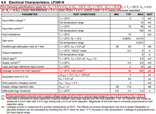
    You want to hold Vin = 15V with Vs=15V and ±15V dual supply rails. The LF398N's input voltage can only operate between -11.5V <= Vin <= 11.5V at the supply voltages. 

    In Hold mode why voltage is increasing in opposite direction (0V to -13V).

    I do not have an explanation why it is charging in the opposite direction yet. The charging (RC) in hold and output voltage should follow the input voltage. I would first lower the Vin voltage to the operating input range. Also, please make sure that your part is authentic that is purchased from the approved vendor. I will also investigate why it is doing that.

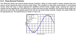
    I only have a theory. The early JFET op amp may not have Phase Reversal Protection Mechanism, but this is just a speculation. The modern op amps have the builtin  Phase Reversal Protection. I have ordered some samples to test the theory. Meantime, if the LF398's input is operated within  -11.5V <= Vin <= 11.5V and do not observe the issue, then this may likely be the case. The samples may take up to a week to receive, and I will check it out after the samples are received.  
     

    Best,

    Raymond 

  • Hi Raymond,

    We have purchased the part from approved vendor only. Kindly share the response as soon as possible.

    Regards,

    Pradeepraj M 

  • Hi Pradeepraj,

    I was wondering that LF398 is operating normally when the input is within -11.5V <= Vin <= 11.5V. The mentioned behavior is shown up when the input common voltage exceeds the operating range specified by the LF398's datasheet.

    Below is the non phase reversal behavior that is described in OPA192 and many other modern op amps. 

    Best,

    Raymond