This thread has been locked.

If you have a related question, please click the "Ask a related question" button in the top right corner. The newly created question will be automatically linked to this question.

LM10: Short circuit detection using LM10.

Part Number: LM10

Hello Team,
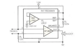
This article shows how to setup a short circuit detection circuit using LM10.

But our use case is little different and we really appreciate your support.

We need to power a daughter PCB with 12V from our back plane PCB.
The power to the daughter PCB will be off until we check the short and reverse polarity of the daughter PCB.
We are using a MOSFET on the back plane PCB to switch the power to the daughter PCB.

We will provide the power to the daughter PCB only after the reverse polarity and the short circuit on the daughter PCB is tested and only if it is OK.

Can I use the circuit below for my purpose.

The output will be isolated and will be fed to an ADC.
Or can anyone suggest a circuit to check the reverse polarity and short circuit on the board?

Looking for your reply.


  • The example circuit triggers when the resistance between the probes is low enough. The LM10 is used because it does not need many external components to drive a buzzer, but this is not necessarily what you want to do.

    What are the electrical characteristics of the daugher board's power lines? How do they differ when they are shorted or reversed? (When you have decoupling capacitors, they will initially look like a short.)

  • Hello Clemens Ladisch,
    Thank you for your reply.

    The power to the daughter board will be 12V.
    The order of this +12V rail and GND can be reversed (Reverse polarity condition).
    This may damage the daughter board.
    If the daughter board is shorted, the resistance between the +12V rail and GND will be zero.
    By measuring this resistance, we can check whether our daughter PCB is shorted or not.
    Is there any others methods to find whether the board is shorted or not?.
    Most of the circuits available in the google check the short by powering the daughter board which may damage the PCB. Link

    can I use a current source to measure the resistance between the +12V and GND just like how a multi meter measures the resistance.
    Is there any other measures to check if the +12V and GND are connected reverse.


  • The only way to measure a resistance (or voltage) is to send some current.

    As I said, a discharged capacitor initially looks like a short.

    What connector type are you using? Can't you change it?

  • Hello Clemens Ladisch,
    Thank you for your quick reply.
    We will have a wire harness between the back plane and the daughter PCB.
    So if any of the +12V or the GND pin in the connector is changed, and the board is powered, the device is going to damage.
    If we have a reverse polarity and short circuit protection before the board is powered, it will be more effective.

    Our board (or any other PCB) will have a resistance of 20K when measured with a multi meter (not powering the device).
    If a constant DC current is allowed to flow through the daughter PCB and if measure the voltage across it (just like how a multi meter works), it will give a zero voltage (0V) if the board is shorted.
    Can you please let me know the effect of capacitor charging with this design? (I hope this will work because it works well with multi meter).

    Also, we have another GND pin in the wiring harness, by measuring the potential between this GND and the +12V or the GND pin (that can change the polarity by mistake), we can confirm whether the board is connected properly or reversely.
    We are planning to use a current source like mentioned in the application note here.
    The current will be set to 1uA, so we will have a voltage of 1V output even if the board resistance is 1M ohms. (Just to confirm we are not exceeding the complaints limit of the current source).
    But the Howland approach seems like a complicated system. Can you please suggest a simple current source that suffice our requirements.

    Can you please comment whether the approach below is suitable for our application or not?. Link


  • The multimeter does not check whether the daughter board actually behaves like a resistor; you might get a different value for a different test current. But the only way to find out how your daughter board behaves is to measure it.

    A Howland current source is very sensitive to (differences in) resistor tolerances, and can make sense only if you need a bidirectional current source. There are simpler circuits for plain current sources/sinks; see, for example, figure 1 on p. 25 of Tips and Tricks for Designing with Voltage References.

  • Hello Clemens Ladish,

    Thank you for your reply.

    If I understand you correctly, I can use a current source to check the resistance/short of my daughter pcb by measuring the voltage accross it.

    Please correct me if I am wrong.

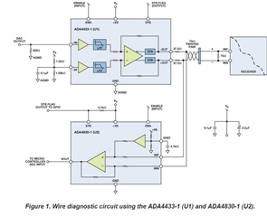
    Also, can you please comment on the circuit using ADA4433

  • Yes, measuring the voltage when a constant current flows allows you to derive the resistance.

    That ADA4830 circuit measure the voltage between the two differential signals. You do not have differential signals; it would be enough to measure the voltage relative to GND.