This thread has been locked.

If you have a related question, please click the "Ask a related question" button in the top right corner. The newly created question will be automatically linked to this question.

OPA4387: OPA4387 Linearity

Part Number: OPA4387
Other Parts Discussed in Thread: OPA4388, , OPA333, OPA388, OPA387, OPA4376, OPA189, OPA187, OPA188, OPA186, OPA182

I'm working on an update to a design that uses the OPA4388, hoping to use OPA4387 as an upgrade but i am running into an issue.

After replacing an OPA4388 on several test boards with OPA4387, I'm measuring an unacceptable amount of non-linearity on the output of the OPA4387. With the 4388, it's linear to within my ability to measure (<10uV at best estimation). With the 4387, I'm measuring diffamp output non-linearity (with respect to input) of ~1mV (~590uV differential at the inputs). This is verified across 4 separate 4387 chips on 4 separate boards.

Input common Mode for this test is from +0.11V to +2.11V, output from +0.182 to 3.5V.
5V supply, linear regulator.
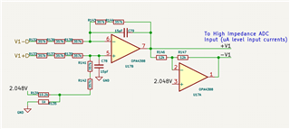
Load on the op-amp output is ~12 kOhm to 2.048V.
Impedance at the inputs is ~400k.
About 6 inches away from a 400kHz switching power supply (does not cause problems for OPA4388 at the least, shielded inductors etc.)

From everything i see in the data sheet, the design shouldn't be a problem, so why am i getting non-linearity vastly exceeding the listed input offset?


  • Jonathan,

    Chopper amplifiers are an excellent choice for low offset, and low offset drift.  However, the chopping calibration process generates current transients on the inputs of the amplifier that translate into input offset when large feedback and input resistances are used.  The maximum recommended source or feedback impedance is different for different models of choppers.  For the OPA388 and OPA387 the maximum recommended impedance is 10k ohms.  Your application exceeds this 10k recommendation by quite a bit, so that is likely what is causing your nonlinearity (i.e. the offset is somewhat related to the input common mode).  Below is a table of max recommended impedances for different chopper options.  Since you are using the OPA388 now, I assume you want 5V options.  The 5V option that is most tolerant of large input impedances is the OPA333.  However, this device has limited bandwidth (GBW = 350kHz), so I don't think this will work for your application.  I am actually surprised that you don't see the issue with OPA388.  I think that perhaps the reason is that the chopping transient translates into an offset but the offset is relatively tolerant of common mode changes so your linearity looks ok.

    Ultimately, I think your best choice would be to use a non-chopper device.  I assume input offset voltage and offset drift is a significant concern and that is why you selected the chopper amplifier.  The OPA4376 is a non-chopper amplifier that is packaged trimmed so that it has low offset and relatively low offset drift.  This device is not nearly as good as the chopper devices from an offset drift perspective, but you will not be getting the specified performance on the choppers due to the chopping transient interacting with the input impedance.   

    Besides the chopping transients, the input bias current of the two choppers is much larger than typical non-chopper CMOS device like OPA4376.  This bias current will also translate into an offset voltage.

    Op amp model

    Max recommended Rs & Rf||Rg

    [kohm]

    OPA189

    1

    OPA388

    10

    OPA333

    1000

    OPA187

    500

    OPA188

    10

    OPA186

    500

    OPA182

    10

    OPA387

    10

    Best regards, Art 

  • Thank you for an excellent answer. I missed the part of the OPAx387 datasheet where they warn against high value resistors (>100kOhm according to the data sheet). This would seem to be my issue, despite matching impedances to deal with higher input impedance as recommended in the data sheet.

    There is no similar warning in the data sheet for the OPAx388 that i can find. I'm presuming that the chopping architecture and the chopping clock rate (150 vs 200kHz) are different enough that the 15pF filtering capacitors are sufficient to hand the transients on the 388 but not the 387. I would have thought 15pF would be enough to satisfy the charge injection requirements.

    Perhaps i would get better performance with a lower input impedance or a larger filter cap with the 388.

    Thank you for the recommendations, but you are correct, the OPA333 misses the requirements in terms of speed (slew rate is much too low).

    Thank you for your assistance.