Other Parts Discussed in Thread: INA238, SYSCONFIG, INA228
HI
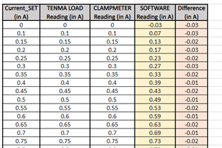
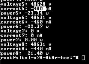
It shows a -30 mA of current without a load. This 30mA difference is seen even when connected to load. please find below details.
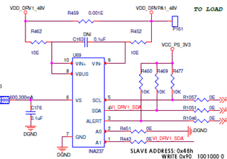
1)1mE shunt resistor/ 5A max current


Please check the attached code
Google Git
Sign in
android / kernel / common / refs/heads/android-mainline / . / drivers / hwmon / ina238.c
blob: ca9f5d2c811bb6ed0eb53f3ee1a3563c5c1d3b0f [file] [log] [blame]
// SPDX-License-Identifier: GPL-2.0-only
/*
* Driver for Texas Instruments INA238 power monitor chip
* Datasheet: https://www.ti.com/product/ina238
*
* Copyright (C) 2021 Nathan Rossi <nathan.rossi@digi.com>
*/
#include <linux/err.h>
#include <linux/hwmon.h>
#include <linux/i2c.h>
#include <linux/init.h>
#include <linux/kernel.h>
#include <linux/module.h>
#include <linux/of.h>
#include <linux/regmap.h>
#include <linux/platform_data/ina2xx.h>
/* INA238 register definitions */
#define INA238_CONFIG 0x0
#define INA238_ADC_CONFIG 0x1
#define INA238_SHUNT_CALIBRATION 0x2
#define INA238_SHUNT_VOLTAGE 0x4
#define INA238_BUS_VOLTAGE 0x5
#define INA238_DIE_TEMP 0x6
#define INA238_CURRENT 0x7
#define INA238_POWER 0x8
#define INA238_DIAG_ALERT 0xb
#define INA238_SHUNT_OVER_VOLTAGE 0xc
#define INA238_SHUNT_UNDER_VOLTAGE 0xd
#define INA238_BUS_OVER_VOLTAGE 0xe
#define INA238_BUS_UNDER_VOLTAGE 0xf
#define INA238_TEMP_LIMIT 0x10
#define INA238_POWER_LIMIT 0x11
#define INA238_DEVICE_ID 0x3f /* not available on INA237 */
#define INA238_CONFIG_ADCRANGE BIT(4)
#define INA238_DIAG_ALERT_TMPOL BIT(7)
#define INA238_DIAG_ALERT_SHNTOL BIT(6)
#define INA238_DIAG_ALERT_SHNTUL BIT(5)
#define INA238_DIAG_ALERT_BUSOL BIT(4)
#define INA238_DIAG_ALERT_BUSUL BIT(3)
#define INA238_DIAG_ALERT_POL BIT(2)
#define INA238_REGISTERS 0x11
#define INA238_RSHUNT_DEFAULT 10000 /* uOhm */
/* Default configuration of device on reset. */
#define INA238_CONFIG_DEFAULT 0
/* 16 sample averaging, 1052us conversion time, continuous mode */
#define INA238_ADC_CONFIG_DEFAULT 0xfb6a
/* Configure alerts to be based on averaged value (SLOWALERT) */
#define INA238_DIAG_ALERT_DEFAULT 0x2000
/*
* This driver uses a fixed calibration value in order to scale current/power
* based on a fixed shunt resistor value. This allows for conversion within the
* device to avoid integer limits whilst current/power accuracy is scaled
* relative to the shunt resistor value within the driver. This is similar to
* how the ina2xx driver handles current/power scaling.
*
* The end result of this is that increasing shunt values (from a fixed 20 mOhm
* shunt) increase the effective current/power accuracy whilst limiting the
* range and decreasing shunt values decrease the effective accuracy but
* increase the range.
*
* The value of the Current register is calculated given the following:
* Current (A) = (shunt voltage register * 5) * calibration / 81920
*
* The maximum shunt voltage is 163.835 mV (0x7fff, ADC_RANGE = 0, gain = 4).
* With the maximum current value of 0x7fff and a fixed shunt value results in
* a calibration value of 16384 (0x4000).
*
* 0x7fff = (0x7fff * 5) * calibration / 81920
* calibration = 0x4000
*
* Equivalent calibration is applied for the Power register (maximum value for
* bus voltage is 102396.875 mV, 0x7fff), where the maximum power that can
* occur is ~16776192 uW (register value 0x147a8):
*
* This scaling means the resulting values for Current and Power registers need
* to be scaled by the difference between the fixed shunt resistor and the
* actual shunt resistor:
*
* shunt = 0x4000 / (819.2 * 10^6) / 0.001 = 20000 uOhms (with 1mA/lsb)
*
* Current (mA) = register value * 20000 / rshunt / 4 * gain
* Power (W) = 0.2 * register value * 20000 / rshunt / 4 * gain
*/
#define INA238_CALIBRATION_VALUE 16384
#define INA238_FIXED_SHUNT 20000
#define INA238_SHUNT_VOLTAGE_LSB 5 /* 5 uV/lsb */
#define INA238_BUS_VOLTAGE_LSB 3125 /* 3.125 mV/lsb */
#define INA238_DIE_TEMP_LSB 125 /* 125 mC/lsb */
static struct regmap_config ina238_regmap_config = {
.max_register = INA238_REGISTERS,
.reg_bits = 8,
.val_bits = 16,
};
struct ina238_data {
struct i2c_client *client;
struct mutex config_lock;
struct regmap *regmap;
u32 rshunt;
int gain;
};
static int ina238_read_reg24(const struct i2c_client *client, u8 reg, u32 *val)
{
u8 data[3];
int err;
/* 24-bit register read */
err = i2c_smbus_read_i2c_block_data(client, reg, 3, data);
if (err < 0)
return err;
if (err != 3)
return -EIO;
*val = (data[0] << 16) | (data[1] << 8) | data[2];
return 0;
}
static int ina238_read_in(struct device *dev, u32 attr, int channel,
long *val)
{
struct ina238_data *data = dev_get_drvdata(dev);
int reg, mask;
int regval;
int err;
switch (channel) {
case 0:
switch (attr) {
case hwmon_in_input:
reg = INA238_SHUNT_VOLTAGE;
break;
case hwmon_in_max:
reg = INA238_SHUNT_OVER_VOLTAGE;
break;
case hwmon_in_min:
reg = INA238_SHUNT_UNDER_VOLTAGE;
break;
case hwmon_in_max_alarm:
reg = INA238_DIAG_ALERT;
mask = INA238_DIAG_ALERT_SHNTOL;
break;
case hwmon_in_min_alarm:
reg = INA238_DIAG_ALERT;
mask = INA238_DIAG_ALERT_SHNTUL;
break;
default:
return -EOPNOTSUPP;
}
break;
case 1:
switch (attr) {
case hwmon_in_input:
reg = INA238_BUS_VOLTAGE;
break;
case hwmon_in_max:
reg = INA238_BUS_OVER_VOLTAGE;
break;
case hwmon_in_min:
reg = INA238_BUS_UNDER_VOLTAGE;
break;
case hwmon_in_max_alarm:
reg = INA238_DIAG_ALERT;
mask = INA238_DIAG_ALERT_BUSOL;
break;
case hwmon_in_min_alarm:
reg = INA238_DIAG_ALERT;
mask = INA238_DIAG_ALERT_BUSUL;
break;
default:
return -EOPNOTSUPP;
}
break;
default:
return -EOPNOTSUPP;
}
err = regmap_read(data->regmap, reg, ®val);
if (err < 0)
return err;
switch (attr) {
case hwmon_in_input:
case hwmon_in_max:
case hwmon_in_min:
/* signed register, value in mV */
regval = (s16)regval;
if (channel == 0)
/* gain of 1 -> LSB / 4 */
*val = (regval * INA238_SHUNT_VOLTAGE_LSB) /
(1000 * (4 - data->gain + 1));
else
*val = (regval * INA238_BUS_VOLTAGE_LSB) / 1000;
break;
case hwmon_in_max_alarm:
case hwmon_in_min_alarm:
*val = !!(regval & mask);
break;
}
return 0;
}
static int ina238_write_in(struct device *dev, u32 attr, int channel,
long val)
{
struct ina238_data *data = dev_get_drvdata(dev);
int regval;
if (attr != hwmon_in_max && attr != hwmon_in_min)
return -EOPNOTSUPP;
/* convert decimal to register value */
switch (channel) {
case 0:
/* signed value, clamp to max range +/-163 mV */
regval = clamp_val(val, -163, 163);
regval = (regval * 1000 * (4 - data->gain + 1)) /
INA238_SHUNT_VOLTAGE_LSB;
regval = clamp_val(regval, S16_MIN, S16_MAX);
switch (attr) {
case hwmon_in_max:
return regmap_write(data->regmap,
INA238_SHUNT_OVER_VOLTAGE, regval);
case hwmon_in_min:
return regmap_write(data->regmap,
INA238_SHUNT_UNDER_VOLTAGE, regval);
default:
return -EOPNOTSUPP;
}
case 1:
/* signed value, positive values only. Clamp to max 102.396 V */
regval = clamp_val(val, 0, 102396);
regval = (regval * 1000) / INA238_BUS_VOLTAGE_LSB;
regval = clamp_val(regval, 0, S16_MAX);
switch (attr) {
case hwmon_in_max:
return regmap_write(data->regmap,
INA238_BUS_OVER_VOLTAGE, regval);
case hwmon_in_min:
return regmap_write(data->regmap,
INA238_BUS_UNDER_VOLTAGE, regval);
default:
return -EOPNOTSUPP;
}
default:
return -EOPNOTSUPP;
}
}
static int ina238_read_current(struct device *dev, u32 attr, long *val)
{
struct ina238_data *data = dev_get_drvdata(dev);
int regval;
int err;
switch (attr) {
case hwmon_curr_input:
err = regmap_read(data->regmap, INA238_CURRENT, ®val);
if (err < 0)
return err;
/* Signed register, fixed 1mA current lsb. result in mA */
*val = div_s64((s16)regval * INA238_FIXED_SHUNT * data->gain,
data->rshunt * 4);
break;
default:
return -EOPNOTSUPP;
}
return 0;
}
static int ina238_read_power(struct device *dev, u32 attr, long *val)
{
struct ina238_data *data = dev_get_drvdata(dev);
long long power;
int regval;
int err;
switch (attr) {
case hwmon_power_input:
err = ina238_read_reg24(data->client, INA238_POWER, ®val);
if (err)
return err;
/* Fixed 1mA lsb, scaled by 1000000 to have result in uW */
power = div_u64(regval * 1000ULL * INA238_FIXED_SHUNT *
data->gain, 20 * data->rshunt);
/* Clamp value to maximum value of long */
*val = clamp_val(power, 0, LONG_MAX);
break;
case hwmon_power_max:
err = regmap_read(data->regmap, INA238_POWER_LIMIT, ®val);
if (err)
return err;
/*
* Truncated 24-bit compare register, lower 8-bits are
* truncated. Same conversion to/from uW as POWER register.
*/
power = div_u64((regval << 8) * 1000ULL * INA238_FIXED_SHUNT *
data->gain, 20 * data->rshunt);
/* Clamp value to maximum value of long */
*val = clamp_val(power, 0, LONG_MAX);
break;
case hwmon_power_max_alarm:
err = regmap_read(data->regmap, INA238_DIAG_ALERT, ®val);
if (err)
return err;
*val = !!(regval & INA238_DIAG_ALERT_POL);
break;
default:
return -EOPNOTSUPP;
}
return 0;
}
static int ina238_write_power(struct device *dev, u32 attr, long val)
{
struct ina238_data *data = dev_get_drvdata(dev);
long regval;
if (attr != hwmon_power_max)
return -EOPNOTSUPP;
/*
* Unsigned postive values. Compared against the 24-bit power register,
* lower 8-bits are truncated. Same conversion to/from uW as POWER
* register.
*/
regval = clamp_val(val, 0, LONG_MAX);
regval = div_u64(val * 20ULL * data->rshunt,
1000ULL * INA238_FIXED_SHUNT * data->gain);
regval = clamp_val(regval >> 8, 0, U16_MAX);
return regmap_write(data->regmap, INA238_POWER_LIMIT, regval);
}
static int ina238_read_temp(struct device *dev, u32 attr, long *val)
{
struct ina238_data *data = dev_get_drvdata(dev);
int regval;
int err;
switch (attr) {
case hwmon_temp_input:
err = regmap_read(data->regmap, INA238_DIE_TEMP, ®val);
if (err)
return err;
/* Signed, bits 15-4 of register, result in mC */
*val = ((s16)regval >> 4) * INA238_DIE_TEMP_LSB;
break;
case hwmon_temp_max:
err = regmap_read(data->regmap, INA238_TEMP_LIMIT, ®val);
if (err)
return err;
/* Signed, bits 15-4 of register, result in mC */
*val = ((s16)regval >> 4) * INA238_DIE_TEMP_LSB;
break;
case hwmon_temp_max_alarm:
err = regmap_read(data->regmap, INA238_DIAG_ALERT, ®val);
if (err)
return err;
*val = !!(regval & INA238_DIAG_ALERT_TMPOL);
break;
default:
return -EOPNOTSUPP;
}
return 0;
}
static int ina238_write_temp(struct device *dev, u32 attr, long val)
{
struct ina238_data *data = dev_get_drvdata(dev);
int regval;
if (attr != hwmon_temp_max)
return -EOPNOTSUPP;
/* Signed, bits 15-4 of register */
regval = (val / INA238_DIE_TEMP_LSB) << 4;
regval = clamp_val(regval, S16_MIN, S16_MAX) & 0xfff0;
return regmap_write(data->regmap, INA238_TEMP_LIMIT, regval);
}
static int ina238_read(struct device *dev, enum hwmon_sensor_types type,
u32 attr, int channel, long *val)
{
switch (type) {
case hwmon_in:
return ina238_read_in(dev, attr, channel, val);
case hwmon_curr:
return ina238_read_current(dev, attr, val);
case hwmon_power:
return ina238_read_power(dev, attr, val);
case hwmon_temp:
return ina238_read_temp(dev, attr, val);
default:
return -EOPNOTSUPP;
}
return 0;
}
static int ina238_write(struct device *dev, enum hwmon_sensor_types type,
u32 attr, int channel, long val)
{
struct ina238_data *data = dev_get_drvdata(dev);
int err;
mutex_lock(&data->config_lock);
switch (type) {
case hwmon_in:
err = ina238_write_in(dev, attr, channel, val);
break;
case hwmon_power:
err = ina238_write_power(dev, attr, val);
break;
case hwmon_temp:
err = ina238_write_temp(dev, attr, val);
break;
default:
err = -EOPNOTSUPP;
break;
}
mutex_unlock(&data->config_lock);
return err;
}
static umode_t ina238_is_visible(const void *drvdata,
enum hwmon_sensor_types type,
u32 attr, int channel)
{
switch (type) {
case hwmon_in:
switch (attr) {
case hwmon_in_input:
case hwmon_in_max_alarm:
case hwmon_in_min_alarm:
return 0444;
case hwmon_in_max:
case hwmon_in_min:
return 0644;
default:
return 0;
}
case hwmon_curr:
switch (attr) {
case hwmon_curr_input:
return 0444;
default:
return 0;
}
case hwmon_power:
switch (attr) {
case hwmon_power_input:
case hwmon_power_max_alarm:
return 0444;
case hwmon_power_max:
return 0644;
default:
return 0;
}
case hwmon_temp:
switch (attr) {
case hwmon_temp_input:
case hwmon_temp_max_alarm:
return 0444;
case hwmon_temp_max:
return 0644;
default:
return 0;
}
default:
return 0;
}
}
#define INA238_HWMON_IN_CONFIG (HWMON_I_INPUT | \
HWMON_I_MAX | HWMON_I_MAX_ALARM | \
HWMON_I_MIN | HWMON_I_MIN_ALARM)
static const struct hwmon_channel_info * const ina238_info[] = {
HWMON_CHANNEL_INFO(in,
/* 0: shunt voltage */
INA238_HWMON_IN_CONFIG,
/* 1: bus voltage */
INA238_HWMON_IN_CONFIG),
HWMON_CHANNEL_INFO(curr,
/* 0: current through shunt */
HWMON_C_INPUT),
HWMON_CHANNEL_INFO(power,
/* 0: power */
HWMON_P_INPUT | HWMON_P_MAX | HWMON_P_MAX_ALARM),
HWMON_CHANNEL_INFO(temp,
/* 0: die temperature */
HWMON_T_INPUT | HWMON_T_MAX | HWMON_T_MAX_ALARM),
NULL
};
static const struct hwmon_ops ina238_hwmon_ops = {
.is_visible = ina238_is_visible,
.read = ina238_read,
.write = ina238_write,
};
static const struct hwmon_chip_info ina238_chip_info = {
.ops = &ina238_hwmon_ops,
.info = ina238_info,
};
static int ina238_probe(struct i2c_client *client)
{
struct ina2xx_platform_data *pdata = dev_get_platdata(&client->dev);
struct device *dev = &client->dev;
struct device *hwmon_dev;
struct ina238_data *data;
int config;
int ret;
data = devm_kzalloc(dev, sizeof(*data), GFP_KERNEL);
if (!data)
return -ENOMEM;
data->client = client;
mutex_init(&data->config_lock);
data->regmap = devm_regmap_init_i2c(client, &ina238_regmap_config);
if (IS_ERR(data->regmap)) {
dev_err(dev, "failed to allocate register map\n");
return PTR_ERR(data->regmap);
}
/* load shunt value */
data->rshunt = INA238_RSHUNT_DEFAULT;
if (device_property_read_u32(dev, "shunt-resistor", &data->rshunt) < 0 && pdata)
data->rshunt = pdata->shunt_uohms;
if (data->rshunt == 0) {
dev_err(dev, "invalid shunt resister value %u\n", data->rshunt);
return -EINVAL;
}
/* load shunt gain value */
if (device_property_read_u32(dev, "ti,shunt-gain", &data->gain) < 0)
data->gain = 4; /* Default of ADCRANGE = 0 */
if (data->gain != 1 && data->gain != 4) {
dev_err(dev, "invalid shunt gain value %u\n", data->gain);
return -EINVAL;
}
/* Setup CONFIG register */
config = INA238_CONFIG_DEFAULT;
if (data->gain == 1)
config |= INA238_CONFIG_ADCRANGE; /* ADCRANGE = 1 is /1 */
ret = regmap_write(data->regmap, INA238_CONFIG, config);
if (ret < 0) {
dev_err(dev, "error configuring the device: %d\n", ret);
return -ENODEV;
}
/* Setup ADC_CONFIG register */
ret = regmap_write(data->regmap, INA238_ADC_CONFIG,
INA238_ADC_CONFIG_DEFAULT);
if (ret < 0) {
dev_err(dev, "error configuring the device: %d\n", ret);
return -ENODEV;
}
/* Setup SHUNT_CALIBRATION register with fixed value */
ret = regmap_write(data->regmap, INA238_SHUNT_CALIBRATION,
INA238_CALIBRATION_VALUE);
if (ret < 0) {
dev_err(dev, "error configuring the device: %d\n", ret);
return -ENODEV;
}
/* Setup alert/alarm configuration */
ret = regmap_write(data->regmap, INA238_DIAG_ALERT,
INA238_DIAG_ALERT_DEFAULT);
if (ret < 0) {
dev_err(dev, "error configuring the device: %d\n", ret);
return -ENODEV;
}
hwmon_dev = devm_hwmon_device_register_with_info(dev, client->name, data,
&ina238_chip_info,
NULL);
if (IS_ERR(hwmon_dev))
return PTR_ERR(hwmon_dev);
dev_info(dev, "power monitor %s (Rshunt = %u uOhm, gain = %u)\n",
client->name, data->rshunt, data->gain);
return 0;
}
static const struct i2c_device_id ina238_id[] = {
{ "ina238", 0 },
{ }
};
MODULE_DEVICE_TABLE(i2c, ina238_id);
static const struct of_device_id __maybe_unused ina238_of_match[] = {
{ .compatible = "ti,ina237" },
{ .compatible = "ti,ina238" },
{ },
};
MODULE_DEVICE_TABLE(of, ina238_of_match);
static struct i2c_driver ina238_driver = {
.class = I2C_CLASS_HWMON,
.driver = {
.name = "ina238",
.of_match_table = of_match_ptr(ina238_of_match),
},
.probe = ina238_probe,
.id_table = ina238_id,
};
module_i2c_driver(ina238_driver);
MODULE_AUTHOR("Nathan Rossi <nathan.rossi@digi.com>");
MODULE_DESCRIPTION("ina238 driver");
MODULE_LICENSE("GPL");
Powered by Gitiles| Privacy| Terms
txt
json
Regards ,
Anoop


