This thread has been locked.

If you have a related question, please click the "Ask a related question" button in the top right corner. The newly created question will be automatically linked to this question.

OPA170: Designing with OPA170

Part Number: OPA170
Other Parts Discussed in Thread: OPA990, TLV9101, TINA-TI

Hello Team,
We are planning to create a constant current source using the opamp OPA170.
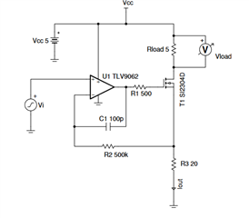
The circuit is as shown below.
The expected current is in the range of 10uA to 2A.
Can anyone comment on the opamp selection?


The current source is for calibrating the current sensor.
Is there any other approaches to calibrate a current source.
Looking for your reply.

  • Hi Sv,

    Is there a reason you are looking at the OPA170 over the OPA990? 

    I know this is a simplified schematic block diagram, but you will likely need to have additional external components to ensure the op amp's stability. Please take a look at the Voltage-to-current (V-I) converter circuit with MOSFET documents we have created to better understand what needs to be taken into account. 

    There's a few other ways of creating a V-I converter. Other methods include using a  BJT, using a Darlington pair, and using a Howland Current Pump architecture. Though with your level of current you need, the Howland Current Pump might be tricky to implement. 

    Best Regards,

    Robert Clifton 

  • Hello Robert,
    Thank you for your reply.
    The Howland current source seems to be very complicated and we don't need that much accuracy.
    The maximum voltage available in our board is 12V.
    The load resistance (here it is the resistance of the hall sensor) is 0.7mOhms.
    The voltage at the non inverting terminal can be varied between 0V and 5V.
    1). What is the maximum current we are able to generate with this setup.
    2). Also, I cannot locate any video/reference showing how to select the R2, R1, and C1 in the design below.

    Can you please guide me?
    Also, most of the MOSFETs are current rated for drain current greater than 1A.
    3). Can I use this circuit with another MOSFET to source a current just above 2A?
    This entire device will be used only for a small amount of time once in an year or so.

    4). Also, can you please explain why you are suggesting OPA990 over OPA170? 
    5). Is current the only parameter to choose between BJT or MOSFET or Darlington transistor pair?


    Looking for your reply

  • Hi SV,

    Lots of great questions: 

    1. The maximum current can be changed depending on the type of MOSFET you use and the voltage you apply to the gate.
    2. It's not very obvious but this covered by the Isolation Resistor Stability Video in the Precision Lab Series
    3. I'm not a MOSFET expert but as long as you aren't violating the MOSFET specs by getting 2A out of it, then this circuit design shouldn't be an issue. 
    4. OPA990 is the next generation of the OPA170. Rail to rail input and improved specs are why I usually recommend OPA990. If you only need 12V then another recommendation is TLV9101. 
    5. I've found that which part the customer uses, whether it's BJT, MOSFET, or Darlington pair, usually comes from a decision they made before they start evaluating which op amp to use to drive. So I'm not sure what drives a customer from choosing one from another. 

    Let me know if this helps clarify things! 

    Best Regards,

    Robert Clifton 

  • Hello Robert,
    Thank you for your reply.
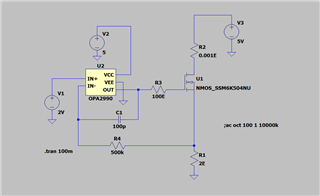
    I have simulated the circuit below using LTSpice.


    The circuit seems to be working.
    Can you please check the circuit and please let me know if there are any comments.

    Looking for your reply

  • Hi SV,

    I'll take a look but I want to add that TI doesn't guarantee that our models will work in any other spice simulator other than Pspice for TI and Tina-TI.

    Best Regard,

    Robert Clifton

  • Hello Robert,
    Thank you for your reply.
    Waiting for your comments

  • Hi SV,

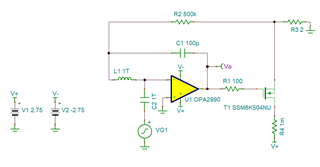
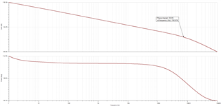
    This ended up taking longer than I intended. For the stability analysis, I had to split the supply rails. I also had to go in and increase the supplies to help the circuit converge. 

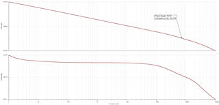
    As you can see here, the phase margin is 32.65 degrees. That's lower than the recommended 45 degrees we say should be the goal. 

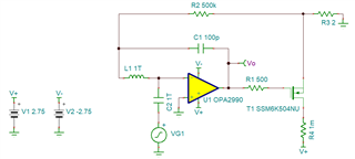
    I then adjusted the value of R1 to be 500ohms rather than 100ohms. As shown below that changes the phase margin to 48.6 degrees. 

    I recommend changing isolation resistor to 500ohms. 

     OPA2990 V to I converter.TSC

    Best Regards,

    Robert Clifton