This thread has been locked.

If you have a related question, please click the "Ask a related question" button in the top right corner. The newly created question will be automatically linked to this question.

INA226: Current monitoring circuit

Part Number: INA226


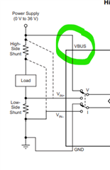
I would like to monitor the current using INA226. There is a block diagram shown in the first page of the datasheet. There is HighSide Shunt and LowSide Shunt. Are these two physical resistors I need to connect in the schematic ?

I guess there has to be are two resistors, one is called HighSide Shunt and the other is called LowSide Shunt. Please confirm. 

How do I connect two resistors provided there are only two pins IN+ and IN-.

IN+ (Pin 10) Connect to supply side of shunt resistor.

IN- (Pin 9) Connect to load side of shunt resistor.

  • Hi John,

    Thanks for the question and using the E2E forum.

    I can understand your confusion here. The resistors are shown as examples, and you would only use one depending on if you're measuring on the high or low side of the load. If you're measuring on the high side, you'd only use the one shunt resistor before the load. If you're measuring low side, you'd only use the one shunt resistor after the load. Either way you only need one shunt resistor, but the drawing is done such that we only had to have one general diagram rather than two.

    Please let me know if you have any other questions.

    Louis

  • Thanks for your reply and making it clear to me that we can measure current only at high side of the load or low side of the load. But the position of the resistor itself look like in series to the load. If it says shunt then I think of parallel, if it says series series then I would think of a resistor in series. Kindly explain how the resistor in series to the load become a shunt resistor. Thanks in advance. 

  • John,

    Yes, the resistor is in series with the load itself, but it is in parallel to the Current Sense Amplifier, hence the term shunt resistor.

    Please let me know if you have any other questions.

    Louis

  • Thanks Louis for your reply. It make the concept clear. 

    I am wondering about the value of the resistor. I am not sure if it is ok to ask here because this is a design parameter. 

    We have a DC to DC converter that provide 4 Amp current with the supply voltage of 5V. There are some LDO connected to the output of LDOs which supply the power to the several ICs. We actually want to measure the total current at the output of the DC to DC converter. We can accept few tens of mV drop in the supply voltage which is not a problem. Any suggestion on the value of the shunt resistor and of what power rating.   

  • One more question. How do we measure the supply voltage at the load ? I guess only the voltage difference across the shunt resistor is amplified by the differential amplifier which is used to measure the current, given that the resistor is known. 

  • John,

    Today is a U.S. holiday but I will get back to your question when I return to the office tomorrow.

    Louis

  • John,

    Any suggestion on the value of the shunt resistor and of what power rating.

    I suggest you watch our video specifically on selecting shunt resistors linked here. It will walk you through all of the care bouts when selecting he appropriate shunt resistor for your specific application.

    How do we measure the supply voltage at the load

    If you look at the diagram on the first page of the datasheet, you can connect the supply voltage of the load the the VBUS connection of the device, then you'll be able to monitor that voltage by reading the VBUS register.

    Please let me know if you have any other questions.

    Louis

  • I started calculating shunt resistance by defining the peak power dissipation across the shunt resistor which is 200 mW. 

    The nominal voltage and the nominal current through the load is 4 A and 5 V. The maximum current through the load is 5 A. 

    Let's calculate the shunt voltage given the power is 200  mA and the max current is 5 A. 

    P = V x I 

    V = P / I 

    V = 200 mW / 5 A

    V = 40 mV

    This shunt voltage 40 mV is well within the input shunt voltage range according to datasheet. 

    Now calculate the value of the shunt resistance. 

    V = I x R 

    R = V / I 

    R = 40 mV / 5 A

    R = 8 m Ohm 

    The value of the shunt resistance is calculated as 8 m Ohm. 

    Now we need to calculate the Current LSB according to equation (2) on page 15/39 of the datasheet. 

    Current LSB = Maximum Current / 2^15

    Current LSB = 5 A / 2^15

    Current LSB = 152 uA/bit 

    Assuming the last two bits are noisy and not very stable. Or we do not want very high precision. Let's ignore the last two LSBs. We multiply by 4 to get new Current LSB. 

    Current LSB = 610 uA/bit 

    Is my calculation are ok until now ? 

  • Now we calculate the Calibration Register value using equation (1). The values of Current LSB and the R_Shunt need to be converted to A/bit and Ohm. 

    CAL = 0.00512 / (Current_LSB x R_Shunt)

    CAL = 0.00512 / (610 /1000/1000 x 8 /1000)

    CAL = 1049 decimal 

  • The resolution of Shunt Voltage Register is 15 bit ? The LSB is 2.5 uV ? 

    Does it means that full scale reading will be 2^15 x 25 uV = 81 mV approx ? 

  • John,

    Yes, all of your calculations look good.

    The resolution of Shunt Voltage Register is 15 bit ? The LSB is 2.5 uV ? 

    Does it means that full scale reading will be 2^15 x 25 uV = 81 mV approx ? 

    This is all correct, and shown in table 10 on page 24 of the DS.

    Please let us know if you have any other questions.

    Louis

  • One last question. How do we calculate junction temperature ? Which power dissipation we use to calculate the junction temperature ?

    If the power dissipation across the shunt resistor is 200 mWatt for example. Do we need to use 200 mWatt multiplied by junction-to-ambient thermal resistance and add to ambient temperature to calculate the junction temperature ?  

    For example junction-to-ambient thermal resistance is 171.4 degC/Watt. The power dissipation across the shunt resistor is 200 mWatt. 

    The junction temperature will be 

    Tj = Tambient + junction-to-ambient thermal resistance x Pd

    Tj = 40 + 171.4 x 0.2

    Tj = 74.2 degC

    Is that correct ? 

  • On the other hand, increasing the value of the shunt resistor in m Ohms will increase the shunt voltage which will decrease the error in current measurement but will increase the power dissipation. What are the consequence of higher power dissipation across the shunt resistor ?
  • John,

    Yes, these calculations are correct to estimate your junction temperature.

  • John,

    Increasing the value of the shunt resistor will increase the power dissipation, which increases heat, and could also mean you have to consider a higher power rated resistor, potentially adding cost. It will also increase thermal noise from the resistor which will manifest into additional system error.

    Louis

  • Thank you very much for your reply. 

    There is still one thing I am not sure about it. I understand that increasing the value of shunt resistor will cause more heat dissipation across the shunt resistance and also crease the shunt voltage that may improve the current measurement accuracy but at the of more heat dissipation across the shunt resistor. 

    Will it also increase the junction temperature of the INA226 ? I am asking this question because the shunt resistor is located physically outside the INA226. So the question is, increasing the shunt resistor value will also increase the junction temperature of the INA226 ? 

  • John,

    It would increase the junction temperature if it were close enough that the heat from the resistor radiated out to the device.

    Louis