This thread has been locked.

If you have a related question, please click the "Ask a related question" button in the top right corner. The newly created question will be automatically linked to this question.

ALM2403-Q1: PSPICE convergence issue

Part Number: ALM2403-Q1

Hi,

We are having trouble performing PSPICE simulations with the ALM2403-Q1 model.

We had a simulation that was running fine with the ALM2402 and switched to the ALM2403 with few adaptations.

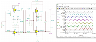
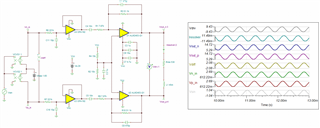
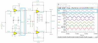
Our current schematic is the following:

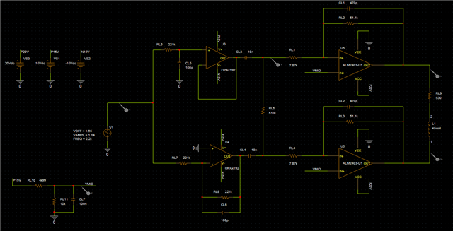
With the ALM2402, the differences were its power supply which was 15V and the RL10 resistance which was 10k.

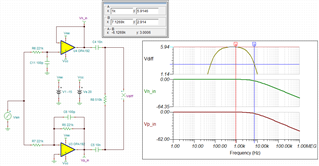
When we run the simulation with the new design, we are having the following errors:

ERROR(ORPSIM-15138): Convergence problem in Transient Analysis at Time =  169.3E-06.
 
  These voltages failed to converge:
 
    V(N52391)                 =   -20.68uV  \  -116.98uV
    V(X_U3.N39892)            =   519.82uV  \   538.42uV
    V(X_U3.N46041)            =     34.66V  \     35.89V
    V(X_U3.N161737)           =    20.70mV  \    24.51mV
    V(X_U4.N39892)            =  -598.85uV  \  -609.97uV
ERROR(ORPSIM-15661): 5 of 5 errors shown. See output file for complete list
 
  These supply currents failed to converge:
 
    I(X_U3.E_E1)              =   -5.880mA  \   -1.089mA
    I(X_U3.E_E3)              =   650.63nA  \   126.55nA
    I(X_U4.E_E1)              =    7.106mA  \   -1.735mA
    I(X_U4.E_E3)              =  -782.23nA  \   180.79nA
    I(X_U5.E_E1)              =   -2.060mA  \   -2.065mA
ERROR(ORPSIM-15661): 5 of 7 errors shown. See output file for complete list

Do you see anything wrong or is there any issue with the model available from your website ?

Best regards,

Clément

  • Hi Clément,

    I do not see obvious issues with the simulation. The error messages indicated that it failed the current convergence issues. 

    I am able to simulate the same circuit via Tina. Here it is the simulation. I do not use PSpice simulator, so I am unable to say what is the issue. In practice, our Tina Spice model should be identical to PSpice model and these models are interchangeable.  Please download the latest PSpice model from our website. 

    ALM2403-Q1 E2E Resolver 02162024.TSC

    Below is an example that is using VCVS to generate the differential input signals. In addition, I have models to generate SPWM input signal to the resolver input. If you are interested, please let me know. 

    Some modification it may improve the circuit. You may consider to increase the capacitive coupling value. At 2.2kHz, the impedance is a bit high at 1/sC = 1/(6.283*2.2kHz*10nF) = 7.2kΩ. This will reduce the output swing a bit. 

    4075.ALM2403-Q1 E2E 02162024.TSC

    At the input, the circuit had differential HPF with 510kΩ. You may consider to lower the cutoff point for 2.2kHz sinusoidal signal. Alternatively, 510kHz may not need it. 

    With some minor changes, the output voltage swings may increase up to +/-12Vpk. 

    If you have other questions, please let me know. 

    Best,

    Raymond

  • Hi Clément,

    Please also see the attached PSpice simulation per your simulation. 

    E2E_Resolver-2024-02-16T19-03.zip

    If you have other questions, please let us know. 

    Best,

    Raymond

  • Hello Raymond,

    I had downloaded the latest ALM2403-Q1 model from the website but as you can see it does not exactly look like yours.

    Did it work out of the box for you ? Because I can see that your simulation is indeed working as intended.

    Thank you,

    Best regards

    Clément

  • Hello and thank you for your detailed answer

    I am able to simulate the same circuit via Tina. Here it is the simulation. I do not use PSpice simulator, so I am unable to say what is the issue. In practice, our Tina Spice model should be identical to PSpice model and these models are interchangeable.  Please download the latest PSpice model from our website. 

    Well me neither but I don't know why it wasn't converging and as I said I had downloaded the latest PSPICE model which does not look alike the one from your pspide simulation.

    Below is an example that is using VCVS to generate the differential input signals. In addition, I have models to generate SPWM input signal to the resolver input. If you are interested, please let me know. 

    That's fine thank you but I wanted to mimic our design, we are generating the sine wave using a DAC from our TMS320 processor with an offset of 1.65V.

    Some modification it may improve the circuit. You may consider to increase the capacitive coupling value. At 2.2kHz, the impedance is a bit high at 1/sC = 1/(6.283*2.2kHz*10nF) = 7.2kΩ. This will reduce the output swing a bit. 

    The design I sent is not fully finalized, it needs to be tuned.

    Our intiial design was targeting LVDT Sensors with a frequency between 2.2kHz and 2.8kHz, but we need to adapt it to work at higher frequencies for resolver as well (about 10kHz).

    Can you elaborate on why you think the impendance is a bit high ?

    We are targeting a lower output swing anyways, the spec is 7.07Vrms.

    At the input, the circuit had differential HPF with 510kΩ. You may consider to lower the cutoff point for 2.2kHz sinusoidal signal. Alternatively, 510kHz may not need it. 

    Hum, I am not sure I understood what you meant you lost me there.

    Best regards,

    Clément

  • Hi Clément,

    had downloaded the latest PSPICE model which does not look alike the one from your pspide simulation.

    Are you able to run the following enclosed model in your simulator. I believed that you are running PSpice industrial version, and the attached .obj files should work in the simulation tool. 

    E2E_Resolver-2024-02-16T19-03.zip

    If you are running PSPICE FOR TI simulation tool, you may need to delete opax192.lib and alm2403-Q1.lib from the configuration files. Please let me know. 

    but we need to adapt it to work at higher frequencies for resolver as well (about 10kHz).

    If the excitation frequency is close to 10kHz, then I typically use 150nF capacitor or 106 Ω @10kHz to couple the input at the inverting input.  

    Hum, I am not sure I understood what you meant you lost me there.

    The following differential HPF + RC LPF look like the following in AC response. I do not think that the filters are optimized yet, and my comments perhaps are premature. 

    If you have other questions, please let me know. 

    Best,

    Raymond

  • Hi Raymond,

    Are you able to run the following enclosed model in your simulator. I believed that you are running PSpice industrial version, and the attached .obj files should work in the simulation tool. 

    Yes, I was able to run the simulation with the file you sent me yesterday, until some point, then after few changes I came into the error again.

    I activated auto converge and it works just fine now, so that was the issue somehow.

    We do run the industrial version as we have a license with our schematic tool.

    If the excitation frequency is close to 10kHz, then I typically use 150nF capacitor or 106 Ω @10kHz to couple the input at the inverting input.  

    Gotcha

    The following differential HPF + RC LPF look like the following in AC response. I do not think that the filters are optimized yet, and my comments perhaps are premature. 

    Yep it definitely isn't, the design I sent you was the one from a previous electronic where generating the excitation for a LVDT sensor with frequencies in the range 2.2kHz to 2.8kHz. Our main problem was anyways the convergence issue.

    I'll open a new question in case I have anything on that matter once I finalize the design.

    Thank you for your help,

    Best regards

    Clément