This thread has been locked.

If you have a related question, please click the "Ask a related question" button in the top right corner. The newly created question will be automatically linked to this question.

TLV9002: TLV9002

Part Number: TLV9002

Thank you for your reply, Leonard Ellis san.

Changed from Japanese to English

tlv9002IDR is an input/output rail-to-rail operational amplifier, but I would like to see how to use it.

We plan to supply 0V and 3.3V to the operational amplifier's power supply voltage and use it as an inverting amplifier.

Configure an inverting amplifier by connecting the positive terminal to common (0V).

Specifically, minus 500V seen from 0V is converted to plus 3V using an inverting amplifier. (G=-3/500)

The common mode voltage range is specified as (V-)-0.1V, and both ± terminals operate at 0V (imaginary short), so I think we can use it without worrying about the power supply. Is there a problem?

Protection is provided in case the op amp loses power.

(Background of the question)

The application example in Figure 9-3 on page 32 of the specifications describes its use in an inverting amplifier.

The positive terminal is DC biased.

I asked this question because I thought that if the positive terminal was at 0 level, it might not work properly.

In past designs, I had never built an inverting amplifier using a single-supply rail-to-rail op amp.

I would like to ask you just in case.

  • Hi Ishikawa-san,

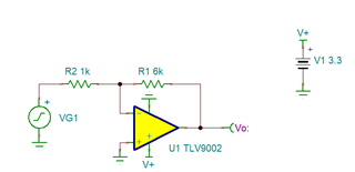
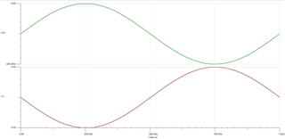
    You might experience a little clipping on the output near ground. I ran a quick simulation under these conditions. 

    TLV9002 Inverting Configuration.TSC

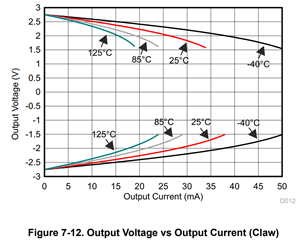
    Another big factor that would affect this signal is the output load. If the output load, as seen by the op amp, is low impedance, aka the op amp drives a lot of current, then your output voltage swing will degrade from this. 

    Best Regards,

    Robert Clifton 

  • Robert sann Thank you for your reply.

    When using a general input rail-to-rail operational amplifier with a single positive power supply,

    we have confirmed that there is no problem with using it with an inverting amplifier.

    (However, the main point is to be careful about the output range)

    This time, it is sufficient to be able to measure between -500V and -50V.

    The input resistance is planned to be 5MΩ, and the output resistance to be approximately 30kΩ.

    Although the conditions are different from the simulation, I think it can be used without problems according to the principle of an inverting amplifier.

    'ARIGATO'

    By the way, what is this simulator?

    Is this something TI is making available to users?

    I usually use PSIM and sometimes LTSpice.

    There was no TLV9002 in LTSpice.

  • Hello Ishikawa-san,

    30kohm resistor is sufficiently large not to cause any clipping on the output due to high current draw. I see no concerns with that nor the other parameters you have described. As long as the op amp is safely insulated from -500V and -50V everything should be fine. 

    The spice simulator we use is either TINA-TI (the one shown here) or Pspice for TI. Both are available for download and I have included the links to them. Both of them have their advantages and disadvantages. One very nice thing that Pspice has is an integrated library that continuously updates!  

    Best Regards, 

    Robert Clifton