Hi Input +/- 10V driving below 10mA Current. i need buffer output same voltage +/-10v i need current 50mA each channel drive output Required.
Please suggest device or circuit Reference this is for signal condition circuit
This thread has been locked.
If you have a related question, please click the "Ask a related question" button in the top right corner. The newly created question will be automatically linked to this question.
8 signal condition inputs driving from AIO Card -10v to + 10v output same out i need output but current 50mA
15v and 28 V i have 12v also ok
In theory, the TLV9034/TLV9534/TLV9634 (they have different speeds) can do this, but with such a high output current, you might get power dissipation problems. You might need to use separate packages (TLV9x32/TLV9x31) that can be better cooled. If that does not help, the OPA2544 has a TO-220 package.
Hello Shivaraj,
There are many answers to this question since it is open ended. I will explain the needed relationships and you may make the best decision.
If this is a DC application (no frequency involved), the op amp does not need large bandwidth (>5MHz). If there is a frequency component, I recommend an op amp with BW 10x the largest frequency of the application.
Large output current requires heat dissipation usually in terms of a thermal pad.
Since the input and output is ±, this requires the op amp be placed in dual supply.
Since there are 8 signal condition inputs, often times it is easier to use 2 quad devices but not required. May use 8 single channel devices, or 4 dual channel devices.
Depending on the power supplies available, rail-to-rail I/O may be required.
For the buffer design, we have an existing circuit here from our reference analog designs: Buffer (follower) circuit
I have created a solution for you but feel free to tweak it around as you see fit:
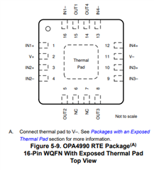
I suggest you use the OPA4990IRTER, it is 4 channel high voltage general purpose op amp that has a thermal pad:

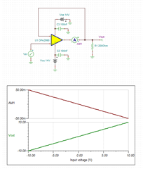
Each channel may be used in the following configuration:

Since you said you have a 28V rail available this may be split into ±14V to provide ample headroom for a ±10V buffer.
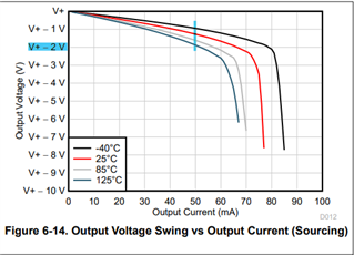
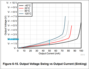
High output current drive degrades the max output the op amp may provide, Figure 6-14 and Figure 6-15 accurately display this.


A safe estimate is to expect 2V from each rail to be limited. This means the application has ±12V of usability, which is ok for the expected ±10V.
Here is the TINA sim I used: 10V_buffer.TSC
All the best,
Carolina