Part Number: OPA2196
Other Parts Discussed in Thread: OPA2188
Dear TI team
I have a question regarding the input tolerance of OPA2196.
The data sheet does not mention
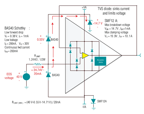
"Input terminals are diode-clamped to the power-supply rails.
Input signals that can swing more than 0.5 V beyond the supply rails should be current-limited to 10 mA or less."
Is it not possible to apply a voltage higher than V+ or less than V- to the input of this amplifier regardless of the current?
Best regards,