This thread has been locked.

If you have a related question, please click the "Ask a related question" button in the top right corner. The newly created question will be automatically linked to this question.

THS3121: Difference between simulation and reality

Part Number: THS3121

Dear Sirs,

I found a big difference in frequency response between the circuit simulated on TINA (I attach the schematic and AC analysis) and the measurements in the real circuit. 

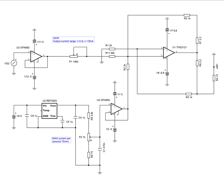
In real circuit, after the flat band of 1MHz, there is instead a progressive increase in gain up to three times in amplitude compared to flat band at around 5-6MHz, and then the expected decrease towards 10MHz and beyond. While the response in simulation presents no overshoot and no resonance at those frequencies. Any suggestions?

Regards.

  • Hi Andrea,

    There are a few things at play when comparing simulated results versus actual results from a circuit. One major difference is that simulation does not account for any real-world parasitic capacitance the circuit has that could cause peaking in its response or any other non-ideal behaviors. Unfortunately, something with regards to the model is that some models do not do a great job at modeling device behavior across more complex configurations and cannot be captured accurately when comparing to the behavior of the actual silicon. This is especially the case with older models like the THS3121. I would like to ask about the circuit you are implementing, is there a reason you are using positive feedback in your design? Are the simulation results providing the results you expected when running AC and transient simulations?

    Best Regards,

    Ignacio

  • Hi Ignacio,

    It seems strange to me that parasitic capacitances can produce such a difference in amplitude in the frequency response.

    However, both the AC simulation and the transient simulation within the flat band agree with the real circuit response.

    Best regards,

    Andrea

  • Hi Andrea,

    Peaking may result from numerous conditions however if the layout of your circuit implements best practices, then there is a chance the model is simply not capturing the response of this more complex configuration accurately and the circuit is slightly more unstable than the simulation is showing. Is there a rough value in the amount of peaking you are seeing in dB from the flat band region?

    Best Regards,

    Ignacio