This thread has been locked.

If you have a related question, please click the "Ask a related question" button in the top right corner. The newly created question will be automatically linked to this question.

OPA2333: SLAU502 - how to change for driving up to 1.0 mA through an LED with 2.85Vf

Part Number: OPA2333
Other Parts Discussed in Thread: TLV9001, LM321LV, LMV321A, TLV8801, OPA333,

Hello,

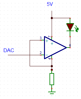
   I need a voltage to current circuit to power a tiny LED from a DAC. DAC output is 0 - 2500mV. The LED has a Vf of 2.85V. Supply voltage (V+ in SLAU502) is 3.3V but I can also make it 5.0V if needed. 

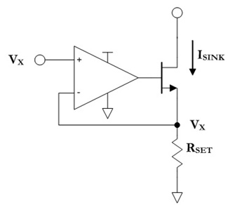
I implemented the circuit in SLAU502 and I think I can leave everything the same except the last stage. Since I only want 1.0mA maximum, Equation 9 is:

RS3 = (Vrs3) / (Iload)

RS3 = 470mA / 1mA

RS3 = 470 Ohms

Is this correct? Or should I have changed the first stage too?

Thanks,

Derek

  • Please note that the control voltage is equal to the voltage drop over the resistor, so the total voltage must be at least 2.5 V + 2.85 V = 5.35 V. Use a smaller DAC output range, or divide the control voltage down.

    SLAU502 creates a current source. But for a LED, you could just as well use a current sink, with a single transistor. See Programmable low-side current sink circuit and How to Generate Current Sources and Sinks of Arbitrary Magnitude. (For a current of 1 mA, you can use a very small transistor like the 2N7002 whose gate has a very small capacitance. In this case, you can connect the gate directly to the opamp and do not need any compensation.)

    And you can save even that transistor by using the opamp's output directly and measuring the voltage drop at the opamp's power supply. Both the LED current and the opamp's supply current flow through the resistor, so the control voltage for a LED current of zero starts a little bit above 0 V. This works only if the opamp's output is strong enough and if its own supply current is not too large; use a CMOS opamp like the LM321LV/LMV321A/TLV9001. With a low-power opamp like the TLV8801, the supply current would be negligible.

  • Hi Derek,

    I like Clemens' suggestions. 

    Regarding the 3.3 V operation, you will leave very little headroom for the FET; since the forward voltage of your LED will be 2.85 V, then you only have 0.45 V of headroom for both the sense resistor and Rdson of the FET.  You should probably reduce the sense voltage on RS3 so that it is closer to 100 mV, then you can still have 0.35 V for the Vds of the FET.  At 1 mA, this should be achievable.

    We are currently putting together a simulation to help the understanding with the correct FET model, please give us 2 days to get back to you with that.

    Regards,
    Mike

  • Hi Derek,

    I made a simulation of the V/I converter circuit, with a maximum output current of 1.25 mA. Due to the threshold voltage of the pMOS used in the reference design (NTF2955), the circuit doesn’t operate with a supply voltage of less than around 4.5 V, so a 3.3V supply will not be high enough. The simulation is set up to run a DC sweep of the supply.


    E2E_SLAU502_3-12-24.TSC

    I suggest selecting a different pMOS that has a lower threshold voltage or reducing Rs2 and Rs3 from 470. If you have any questions, please let us know.

    Best,

    Alex

  • Hello, I have 5V available as a supply so I'll just use that. For the FET I realized that the orginal one I selected had a fairly high threshold voltage, so how about this one instead?

    https://www.diodes.com/assets/Datasheets/DMN53D0L.pdf

    For the op-amp, would OPA333 work? (17uA supply current, up to 5mA output current, rail-rail I/O, 5.5V max)

    So reading through slaa868.pdf,

    If I set DAC output to 5.0V then the Rset = (Vdac / Iout) = (5000mV / 1mA) = 5k, is that correct?

    I found slaa868.pdf to be rather lacking because it does not specify how to select Q1. 

    I also read through SSZTCA8 which confirmed this design.

    For this application we want the output current to be very stable. It's used as an illumination source for imaging cells. Aside from selecting a Rset with high tolerance and low temperature coefficient is there anything else I should do to minimize current fluctuation?

    Thank you,

    Derek

  • The FET must have a threshold voltage low enough for the opamp, but it should also have a small input capacitance. The DMN53D0L is OK; other FETs with even smaller capacitance would be RK7002BM/NX138AK/NX138BK/SSM3K15F/NX3020NAK/DMN63D8L.

    (In most applications, Q1 must be chosen to support a high LED current, which requires tradeoffs regarding gate voltage and capacitance. This is not a consideration here.)

    The OPA333 will work.

    When you have a 5 V supply, a voltage drop of 2.85 V over the LED, and a little bit over the FET, then you do not have more than 2 V available for the voltage drop over the resistor. Use at most 2000 mV. (If you want to use the full DAC range, use a lower reference voltage for the DAC; or divide its output down.)

  • Yes, in agreement with Clemens the circuit will not work with both the supply and DAC at 5V, so I would suggest using a peak DAC voltage of 2.5 V, as well as using a 2.5k resistor instead of a 5k. You can also lower the resistors connected to the positive rail (Rs2 and Rs3) which would give you more headroom.

    Regarding temperature considerations, the OPA2333 is a great choice because its zero drift and has a low offset voltage.

    I went ahead and modified the TINA sim with the new values, and if you have any other questions, let me know.

    E2E_SLAU502_3-18-24.TSC

    Kind regards,

    Alex