This thread has been locked.

If you have a related question, please click the "Ask a related question" button in the top right corner. The newly created question will be automatically linked to this question.

INA260: INA260 mid-side monitor ?

Part Number: INA260
Other Parts Discussed in Thread: INA240

Hello,

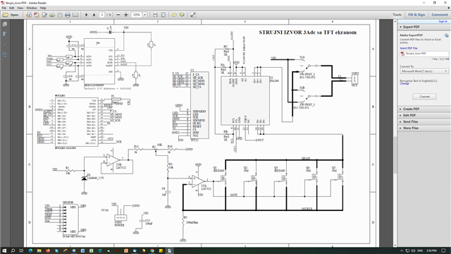
I built a current source and used INA260 to measure current. The INA260 is placed between load and FET's, so neither IN+ is on VCC, neither IN- on GND. My measurement are different then values from external ampere meter about 30-50%. Can INA260 can be placed like this or only on high- and low- side measurement mode ?

Photo of circuit is below.

BR,

Sasa Dimitrijevic 
  • "Low-side" and "high-side" are just hints on what the common-mode range of the amplifier is. It refers to low voltages and high voltages, without a specific range for "low" or "high".

    The INA260 allows input voltages anywhere in the range between 0 V and 36 V.

  • HI All, 

    Clemens is correct on this. Thank you Clemens! 

  • Hi All,

    I re-wired connection this morning and find out that it works correctly only when is on high- or low- side, e.g. only when one of the terminals are on  fixed voltage, VCC or GND.

    If I insert somewhere between in circuit branch, like in my schematic, it does not work well and show error of 50%. 

    Is there any explanation for this middle-side connection issue , theoretically or empirically from your side ?

    Thanks.

  • Hi Sasa, 

    I am looking into this and will get back to you tomorrow. 

  • Hi Sasa, 

    It seems you are using the INA260 in-line with a PWM input CM voltage. The INA260 was not designed for this, it was only designed for a stable DC common mode voltage. You should consider one of our devices that include PWM enhanced rejection ratio such as the INA240 or INA241. When using a low/high side device on a PWM Vcm, then you are going to be limited by the device's AC CMRR, which will be pretty bad with fast switching square wave Vcm. Every time Vcm changes rapidly, there will be an output disturbance that will take time to settle. So if they are not waiting long enough, they will get an unsettled (inaccurate) measurement. On top of all of this, there is a risk of inductive kickback pulling the Vcm < -0.3V which could break the device. So this is another reason not use this device (or any device rated to 0-V Vcm min).

    Best,

    Mohamed