This thread has been locked.

If you have a related question, please click the "Ask a related question" button in the top right corner. The newly created question will be automatically linked to this question.

OPA360: OPA360 / OPA361 Design Questions

Part Number: OPA360
Other Parts Discussed in Thread: OPA361, , OPA316, OPA858DSGEVM, THS7372, THS7368, THS7364, THS7360

Dear Team,

we have some design questions regarding OPA360/OPA361

1) If the OPA needs to be enable all the time is it better to leave enable pin floating or tie directly to V+ ( 3.3V)?

2)If the SAG function of OPA360 is not used, what is the proper termination of this pin

3)if the Rset function of OPA316 is not used, what is the proper termination of the pin, floating or tie to GND?

4)Please can you recommend decoupling caps for the V+ pin @ 3.3V ? do we need to filter this supply with inductor or ferrite bead?

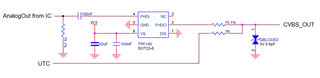
5) Her is or reference schematic but it is for AHD, and we only need to use CVBS and thus want to replace TPF140 with OPA360 / OPA361

6) we want to use following ESD diode to replace GBLC03CI, is it ok?

ESD451DPL or 

TPD1E0B04DPL which is more recommended?

  • Hello D,

    Please see the following answers to your questions;

    1. You should drive and not float the enable pin; please drive to greater than 1.6V.  You can tie to positive 3V3 supply.

    2. You are able to float the SAG pin; terminating the pin to GND would allow for current flow and affect the feedback loop.  As you can see, some applications tie SAG directly to output (see Figure 16), which you may also try.  The purpose of the pin is to tie it to the output via a 22uF capacitor to assist with sag correction.  

    3. You can float the Rset pin, as it is not used for the OPA361 but for the adjacent part OMAP2420.  The internal 4kOhm resistor does not affect OPA361 performance.

    4.   This depends on your supply circuitry; if it is noisy you may need to filter more strongly.  It is typical to place a bulk (uF) capacitor near the power supplies as well as a smaller (nF) capacitor near the op-amp supplies.  Examples of this can be found on other TI HSAMPs EVMs, such as the OPA858DSGEVM.

    5. I do not see a problem using OPA360/1 for CVBS, as long as you recognize you may need external filtering.  CVBS has a lower frequency signal than Full HD.  You can observe this on parts such as the THS7372, which have different low pass filters (LPF) for CVBS and HD channels.

    6. I do not have expertise on TVS diodes; from what you shared the ESD451DPL is a decent cross to the GBLC03CI.  You may ask this to the TVS protection diodes team. You could ask with either of the TI diodes you proposed.

    Thank you D for your questions.

    Best,

    Alec

  • Hi Alec,

    thank you for the replay, i did some more research regarding OPA360/1.

    1) I found in DS of OPA360 page6 ( Enable/Shutdown) section

    "If the Enable pin is not connected, internal pull-up circuitry will enable the amplifier."

    But it is probably better to tie it to 3.3V

    2) As we are using it as DC-coupled output we don't need SAG, what is better for performance from your experience to tie SAG to OUT our leave it floating?

    3)OK

    4) Please can you provide the link to the TI HSAMP EVM OPA858DSGEVM? Also do you know other EVM where OPA360/1 is used?

    5)

    5a) Regarding frequency for CVBS , as per DS OPA361 has slightly better frequency response than OPA360, if i'm reading correctly?

    for OPA361 f-3dB is typ 9MHz, and that should be no problem for 480i and 576i as the max freq is 9MHz,but for 480p and 576p the max freq is 13.5MHz

    do you see a problem with that?

    5b) What do you mean by "as long as you recognize you may need external filtering" in your sentence: ?

    " I do not see a problem using OPA360/1 for CVBS, as long as you recognize you may need external filtering."

    5c) if you look at our schematic , the input to OPA360/1 is AC coupled with 100nF , do you see any problem with this?

    I read in this forum post that OPA360/1 was not designed to be AC coupled on input but rather DC coupled

    https://e2e.ti.com/support/amplifiers-group/amplifiers/f/amplifiers-forum/746165/opa360-aging-test-output-vedio-abnormal

    And as you see we have our DAC out , then 75Ohm pull-down, then 100n AC coupling and then input to OPA360/1

    And i'm not shore in what case do we use AC coupling or DC coupling on the input of video amp? 

    5d) And i also noticed that OPA360 doesn0t have pull-down on the input while OPA361 has a 500Ohm pull-down

    5e) in case if we use OPA360/1 as dc couple on input, do we need the 75Ohm termination of our DAC output?

    Best Regards,

    d.

  • Hello D,

    I will look into your questions and get back to you early next week.

    Best,

    Alec

  • Hello D,

    1) I found in DS of OPA360 page6 ( Enable/Shutdown) section

    "If the Enable pin is not connected, internal pull-up circuitry will enable the amplifier."

    But it is probably better to tie it to 3.3V

    - I agree, you may float it but I recommend tying the pin to Vsupply if you can do so.

    2) As we are using it as DC-coupled output we don't need SAG, what is better for performance from your experience to tie SAG to OUT our leave it floating?

    - You can float the SAG pin.

    3)OK

    - Slight smile

    4) Please can you provide the link to the TI HSAMP EVM OPA858DSGEVM? Also do you know other EVM where OPA360/1 is used?

    https://www.ti.com/tool/OPA858DSGEVM - the OPA858DSGEVM is not the same package as the OPA360/361, but is a good example of high-speed PCB design.  

    I would recommend either the DEM-OPA-SC-1A-EVM or the LMH730165 EVM.

    5)

    5a) Regarding frequency for CVBS , as per DS OPA361 has slightly better frequency response than OPA360, if i'm reading correctly?

    for OPA361 f-3dB is typ 9MHz, and that should be no problem for 480i and 576i as the max freq is 9MHz,but for 480p and 576p the max freq is 13.5MHz

    do you see a problem with that?

    - Is your application using both interlaced (i) and progressive (p) video scanning methods?  Our other products for SD video and CVBS have internal filters at 9.5MHz, so I do not think there is a general problem here.  You may have to test and see if your application is using progressive scanning.  

    5b) What do you mean by "as long as you recognize you may need external filtering" in your sentence: ?

    " I do not see a problem using OPA360/1 for CVBS, as long as you recognize you may need external filtering."

    - This statement was made in error, I was thinking about our other devices which may not have internal bandwidth filters or limitations.  Some TI video amplifiers have pass-through, where there is not an internal low pass filter and the full device bandwidth is available.  These parts, like the THS7360, THS7364, and THS7368, have internal filters with bypass for standard definition and high definition channels.  The SD channels here are 9.5MHz.

    5c) if you look at our schematic , the input to OPA360/1 is AC coupled with 100nF , do you see any problem with this?

    I read in this forum post that OPA360/1 was not designed to be AC coupled on input but rather DC coupled

    https://e2e.ti.com/support/amplifiers-group/amplifiers/f/amplifiers-forum/746165/opa360-aging-test-output-vedio-abnormal

    And as you see we have our DAC out , then 75Ohm pull-down, then 100n AC coupling and then input to OPA360/1

    And i'm not shore in what case do we use AC coupling or DC coupling on the input of video amp? 

    - If your DAC is a current DAC, you can use a capacitor in parallel with your 75 Ohm resistor.  This is discussed in the OPA360 datasheet.  This is shown in Figure 1. Filter Structure of OPA360.

    - I do not think should AC couple either part's input.

    - I am not sure which device, OPA360 or OPA361, you intend to use for your system.  The devices both have fixed gains which are different, one is 2V/V and one is ~5V/V.    

    5d) And i also noticed that OPA360 doesn0t have pull-down on the input while OPA361 has a 500Ohm pull-down

    - The OPA361 integrates this resistor, while it should be placed separately for the OPA360.

    5e) in case if we use OPA360/1 as dc couple on input, do we need the 75Ohm termination of our DAC output?

    - Both parts have internal series resistors following the input pins.  This appears to be both for internal gain-setting and input impedance structure.  However you may need the 75 Ohm termination if there is a distance between the DAC and the video amplifier.  The 75 Ohm termination helps impedance match the output of the DAC to the input of the video amplifier.  Depending on how long of a trace this signal is travelling along, you may need the termination resistor.

    Thank you for your questions D.

    Best,

    Alec