


I initially brought a current sensor from Adafruit that used an INA228 chip. After some challenges, I managed to get the I2C communication going and was able to read data from the registers. I cleaned up my code and made a custom board that has 16 of these sensors.
I only soldered one of the INA 228 sensors on my custom board and am trying to see if I can read the registers using the same code. For some reason, my code works on the adafruit sensor but not on my custom board. Not sure why. I scoped the I2C lines using a logic analyzer. I have attached the captures to this message and also listed the data being transmitted below. Can anybody please explain what I missed on my custom board here?
Working Data stream: Start -> 0x40 Write (Slave address) -> ACK -> 0x06 (Temp register) -> Stop || Start -> 0x40 Read -> ACK -> 0x0B -> ACK -> 0xC8 -> NAK -> Stop
Here clearly the data from the register is 0x0b, 0xC8. This translates roughly to 23.56 C. This works. No issues (I think).
Not working Data Stream: Start -> 0x40 Write -> ACK -> Stop || Start -> 0x40 Read -> ACK -> 0x00 -> ACK -> 0x00 -> NACK -> Stop
|| Here represents a small pause.
Why is the Master not writing 0x06 (register to read) in the custom board case when I am using the same code? Why is the SDA line always low? Is this a hardware or firmware issue?
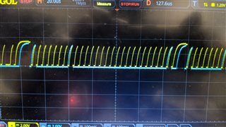
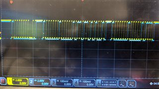
Not working screenshot:
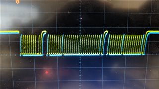
Working screenshot:

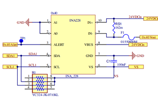
INA 228 Circuit:
Adafruit sensor: www.adafruit.com/.../5832
Note:
The working board had 4.7K pull-up resistors. I tried 4.7K, 24k and 2.4K pull up resistors. Neither of them worked so far. Not sure if it's even a pull up resistor thing.
Thank you
Varun R

