This thread has been locked.

If you have a related question, please click the "Ask a related question" button in the top right corner. The newly created question will be automatically linked to this question.

OPA357: Buffer for a REF3030 go wrong

Part Number: OPA357
Other Parts Discussed in Thread: REF3030, , TLV9101, OPA310

Hello, 

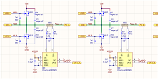
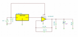
I'm using an OPA357AIDBVR (IC18) to buffer a REF3030 chip. Below I show all the circuits that have interface with the AVREF:


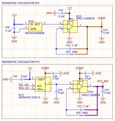
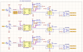
The problem: the AVREF should follow the positive input voltage of the OPA357AIDBVR, therefore AVREF should be 3V, but actually the measured voltage in AVREF is around 2.66V instead of 3V in the real circuit.
When I desolder the OPA357AIDBVR (IC18) and connect AVREF to 3V3 bus, everything works ok.

Using TINA, it shows the output's expected behave, with a 3k Ohm resistor put to simulate the load (around 3k5 Ohm):


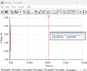
Why is this so different from reality? I've changed the OPA for another brand new one and got the same result. Could you tell what should be the problem here?

Regards.

  • There are lots of capacitors connected to AVREF. Please check that it is not oscillating. (See section 7.3.10 of the OPA357 datasheet.)

    The OPA357 can drive large output currents, but as shown in figure 21, it has problems near the rails. Do you get a better voltage if you disconnect IC18's output from AVREF? The REF3030 itself has a smaller dropout voltage, so it is possible that you do not need a buffer at all; try bypassing IC18. Alternately, try replacing the OPA357 with an amplifier with stronger rail-to-rail outputs like the TLV9101‍IDBVR or OPA310‍IDBVR.

  • Hello Clemens,
    I've done a simulation with the capacitance of 1.5uF in parallel to the resistive load in TINA (the real capacitance is around this value), but it shows a stable 3V output, so maybe the capacitance isn't likely to be the problem. Maybe the problem is related to the proximity with the V+ rail voltage.
    Also, trying to drive the circuit directly with the REF3030 gives a AVREF of around 2.5V, so it get a undesired voltage drop, meaning that I will indeed need a buffer. Where in the datasheet I was supposed to search for the info to make sure the TLV9101‍IDBVR or OPA310‍IDBVR will work? I'm asking this because for what i've read in the OPA357AIDBVR it was supposed to work with the current demand way lower than 100mA but it didn't?

    Best regards

  • I do not know how accurate the simulation models are.

    The OPA357 (figure 21) shows an offset from the rails even at 0 mA. The other opamps (e.g., TLV9101: figure 6-14) have true rail-to-rail outputs:

  • Hi Emanuel,

    Clemens highlighted an important point with the graphs he shared, which show that as you load the amplifier the max output voltage of said amplifier will decrease and this drop in output voltage swing varies for different devices. The output voltage swing vs output current curves can be found in most datasheets. When considering all the ICs this OPA357 has to power up, which even if in standby mode require some current (Iq), how much current are you expecting to pull from the OPA357 AVREF output? I saw you simulated to be pulling 1mA, which is not enough to load the amplifier and affect its output swing. 

    Best Regards,

    Ignacio