Part Number: TLC2262
Other Parts Discussed in Thread: TLV9352
The power supply and GND pins of TLC2262 are connected to +5V and -5V respectively.
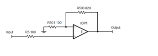
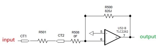
The test circuit is as follows:
The input terminal uses a signal generator to generate a square wave with an amplitude of 0.2V and a frequency of about 1K for input (as shown in Figure 1).
When R501 is 5K, its voltage output is shown in Figure 2
input:
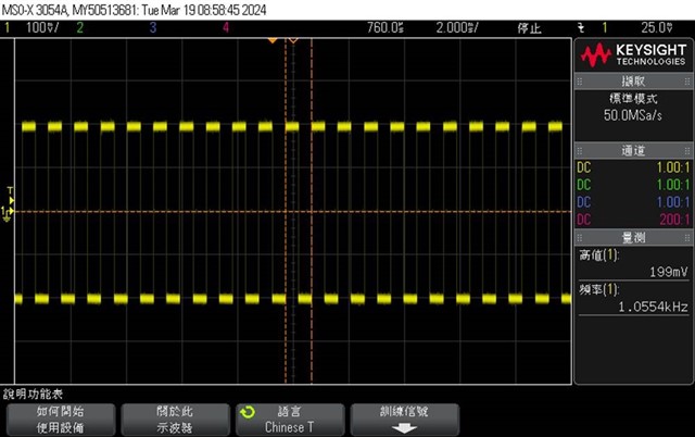
Figure 1
output:
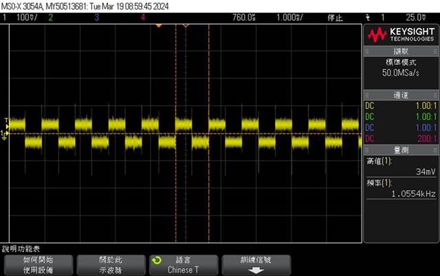
Figure 2
At this time, when R501 is changed to 100 ohms, the waveform at the input end becomes Figure 3 below, and the waveform drops from 200mv to 115mv.
I can’t understand why the input waveform becomes smaller when the resistor R501 becomes smaller? How to solve it?
input:
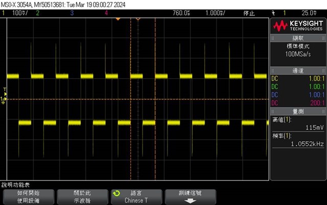
Figure 3
output:
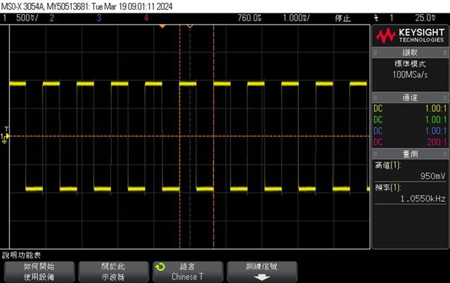
Figure 4