- Ask a related questionWhat is a related question?A related question is a question created from another question. When the related question is created, it will be automatically linked to the original question.
This thread has been locked.
If you have a related question, please click the "Ask a related question" button in the top right corner. The newly created question will be automatically linked to this question.
Dear TI Teams,
One of our new project need to use a 65W adapter (20V/3.25A). We to detect the signal of the adapter, when the adapter is detected to be inserted, EC will enable INA300 to achieve real-time monitoring of the pressure difference at both ends of PR85 (33mohm).
When the current flowing through both ends of the resistor reaches 3.25A, INA300 pulls down alert #, turns off PQ4945, and thus turns off PQ3. Does this solution feasible? If not, do you have anly better suggestion for this application?
The schematic is show as below, can you help to check it?
Thanks,
Kind Regards
Hello,
Thank you for your post. I would like some clarification on your design goals.
Are you sensing bidirectional current or unidirectional current? If bidirectional, then you will need a second INA300.

I would also like to know why you placed the series resistor with the open drain output? Are you trying to slow down the alert signal before shutting off PQ4945?
I see that you are protecting the VGS of PQ3 to 25V, good.
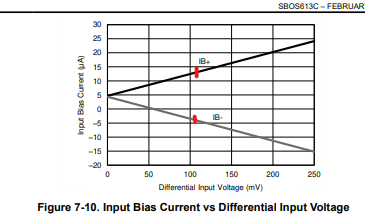
The input filter will improve noise immunity. Please take note of the expected input bias current at the shutoff differential voltage of ~107mV.

Best Regards,
Joe
Hi Joe,
Thanks a lot for your reply. The answer for your question is as below:
Are you sensing bidirectional current or unidirectional current? If bidirectional, then you will need a second INA300.
We are just sensing unidirectional current.
I would also like to know why you placed the series resistor with the open drain output? Are you trying to slow down the alert signal before shutting off PQ4945?
PR82 will be deleted in the future, and PC12491 (normally empty) is reserved to prevent PQ4945 from turning off too quickly, which may affect the Gate end of PQ3 due to parasitic inductance in the wiring.
The input filter will improve noise immunity. Please take note of the expected input bias current at the shutoff differential voltage of ~107mV.
Currently, we have reserved a 0 ohm resistor in IN+ and IN-. And we will pay attention to the impact of input bias current if we need to adjust this resistor in the future.
Thanks,
Kind Regards
Hi Lumina,
Please keep me posted on the design progress if you need simulation or hardware support. For now, I will close this thread as everything looks good from my end. Respond to this thread or create a new one for additional support.
Thanks again for your post,
Joe