XTR300: schematic review

Part Number: XTR300

Tool/software:

Hi team,

Could you please help review below schematic:

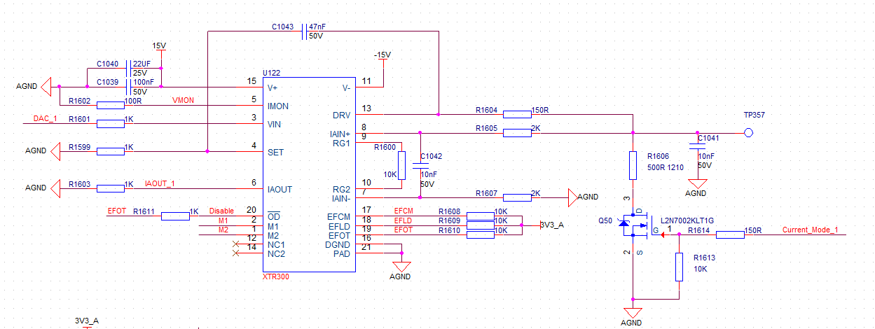
Customer wants to achieve 4~20mA current output and 0~10V voltage output.

Q1: Is this circuit can achieve 4~20mA current output and 0~10V voltage output.

Q2: Can customer use 0~12V power supply, just connect 0V to IC's V- pin?

  • Hi Gary, 

    I have a few questions to clarify about the schematic: 

    • What is connected to M1 and M2? 
    • Where is voltage output going to be measured? At IAOUT_1? And is current output measured at Current_Mode_1?
    • What is the Vin range from the DAC going into the input of XTR? 

    There are also a few corrections from this schematic that need to be made: 

    • Thermal pad must be connected to V-, not ground. Please update this in the design. 
    • IMON resistor (R1602) is recommended to be in the kohms range, please see the recommended circuit considerations in the datasheet on page 17. 

    • V- rail needs decoupling capacitors similar to V+, this is not visible in the schematic so I am making a note of it. 
    Q2: Can customer use 0~12V power supply, just connect 0V to IC's V- pin?

    It is not recommended to use a single supply power supply for this design that the customer needs as the output swing range will be limited. So it is important to have enough headroom so you can achieve the full output range desired. 

    Regards,
    Ashley

  • Hi Ashley,

    M1 and M2 are connected with M0 MCU.

    Vout should be relevant to Rset: R1999, Rgain: R1600 and Vin.

    Iout should be relevant to Rset and Vin.

    Input range is 0~10V.

    Q3: Customer want to know if output of XTR300 can be used for input voltage sensing. We see there is a output disable mode in page 19 of datasheet,.

    Q4: Can TP357 afford +24V voltage and w/o damage?

  • Hi Gary, 

    Is the input range 0-10V for voltage mode or current mode? I am calculating the transfer function for Vout and Iout and do not see how the input range can correlate for 4-20mA or 0-10V for either mode. 

    The output disable mode can be controlled via OD pin. I am not sure I understand what you mean by using the output for input voltage sensing. Could you clarify? 

    The XTR output should be able to withstand the 24V with the protection scheme currently used - please see this section of the datasheet as reference: 

    Regards,
    Ashley