This thread has been locked.

If you have a related question, please click the "Ask a related question" button in the top right corner. The newly created question will be automatically linked to this question.

INA849: The lowest noise configuration with INA849 AMP

Part Number: INA849
Other Parts Discussed in Thread: JFE2140

Hi,

I want to know the proper configuration to connect a low-frequency antenna (15mH@5-5K ohms) to an INA849 amplifier with a required gain of around 200 and a bandwidth of approximately 400kHz, while minimizing noise.

all regards.

Itamar Shamay

HW Engineer

 Exodigo.

  • Hello Itamar, 

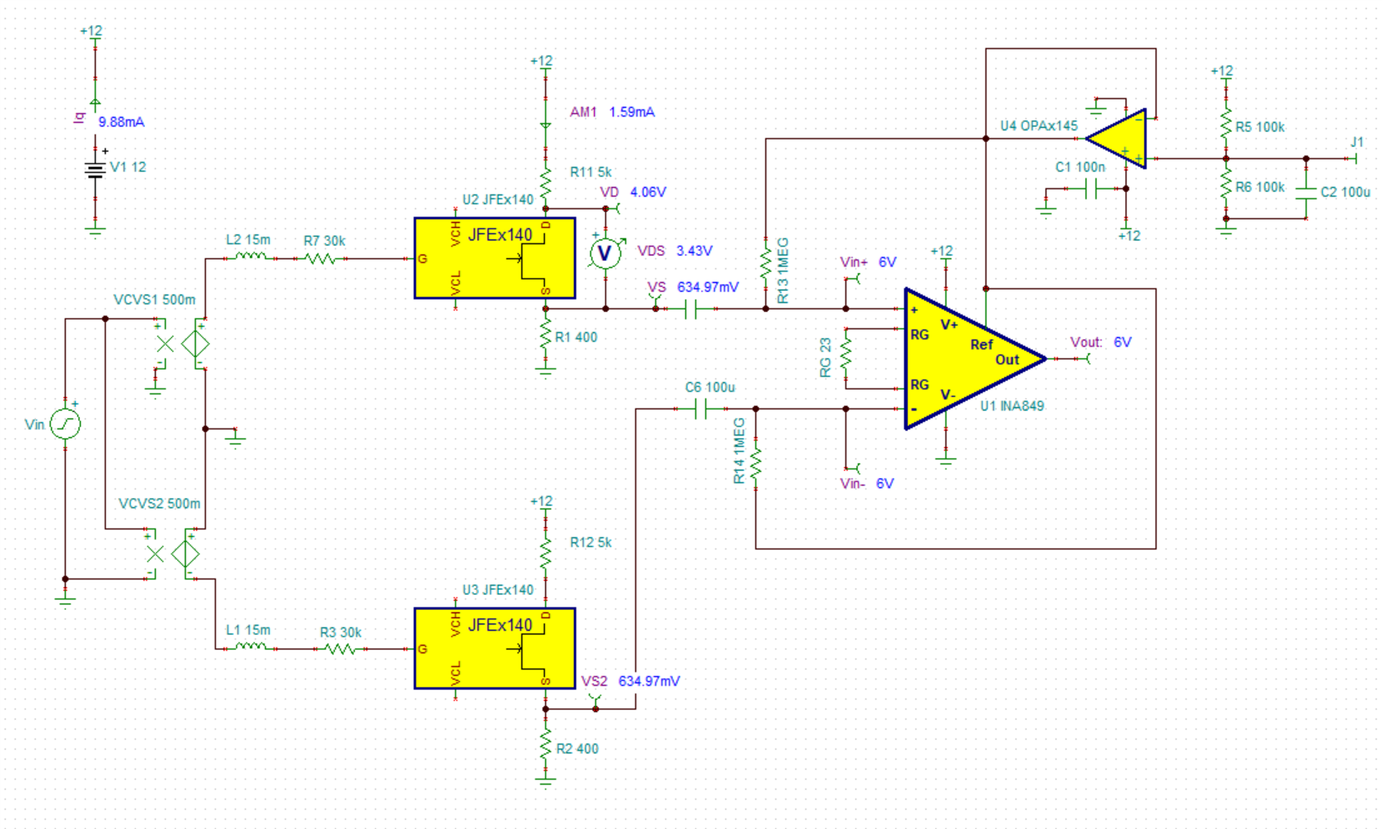
    When using an inductive sensor such as an antenna, the current noise of a bipolar input stage such as the INA849 can be challenging. Recently we have released discrete JFET devices and when paired with the INA849 I am able to achieve very low noise due to the high input impedance of the JFET. The JFE2140 is a dual JFET device and can be used in a source follower configuration as shown below. 

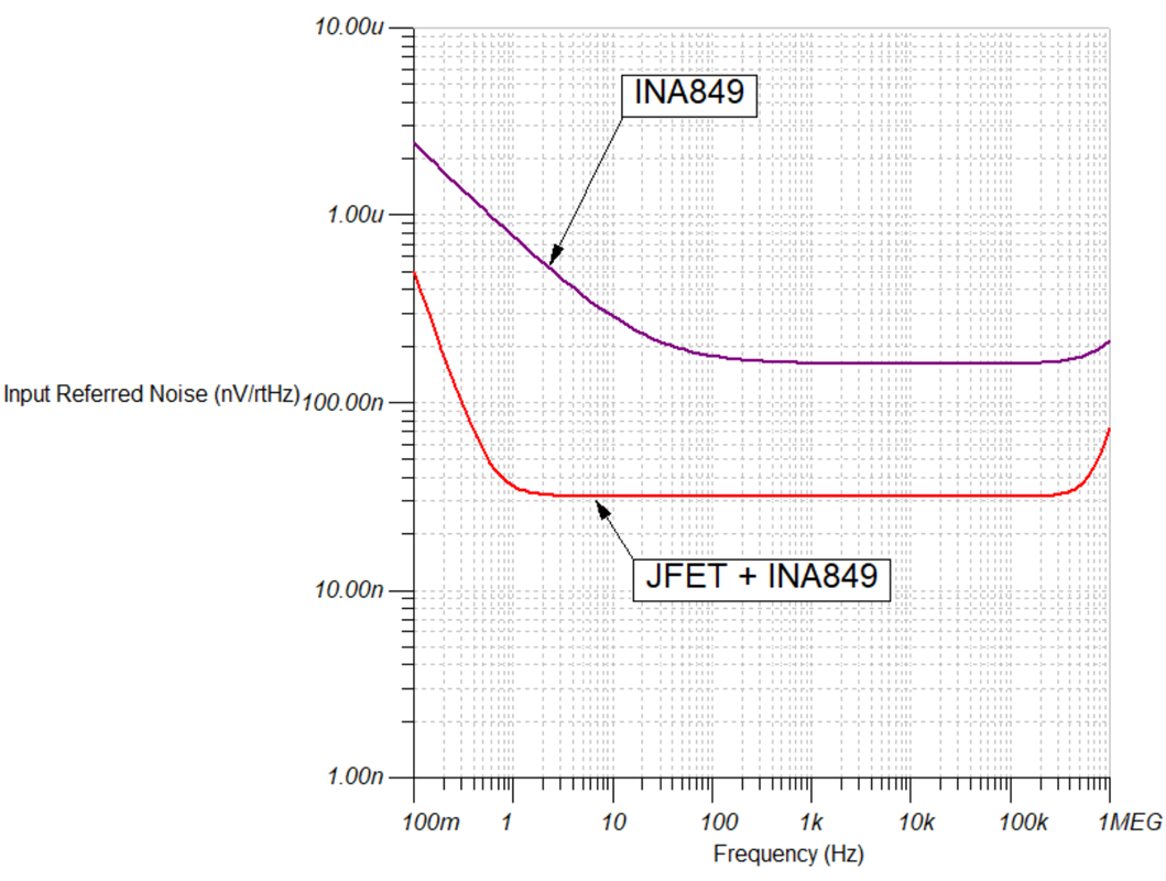
    I ran two simulations and they are attached to the bottom of this post. I compared the INA849 alone and then replaced the front end of the INA849 with the JFET source followers. You can see the noise comparison below. There is an 80% reduction in noise when using the JFETs for a trade off of 47% increase in Iq. The INA849 circuit draws 6.71 mA vs the JFET circuit draws 9.88 mA. 

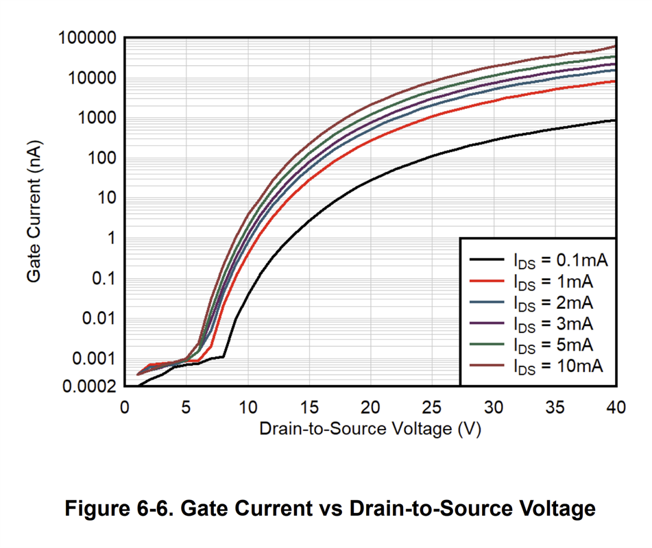
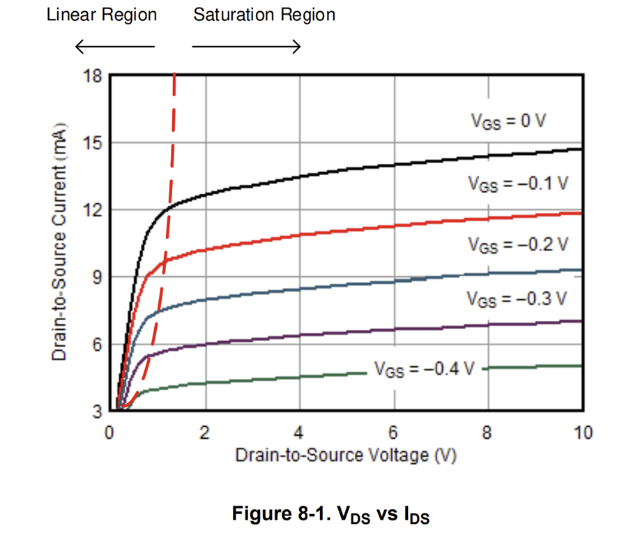
    Some things to note. I kept the VDS voltage large enough to stay in saturation but small enough to keep the gate current low. The goal was to reduce current noise. Keep the VDS voltage in mind when designing. 

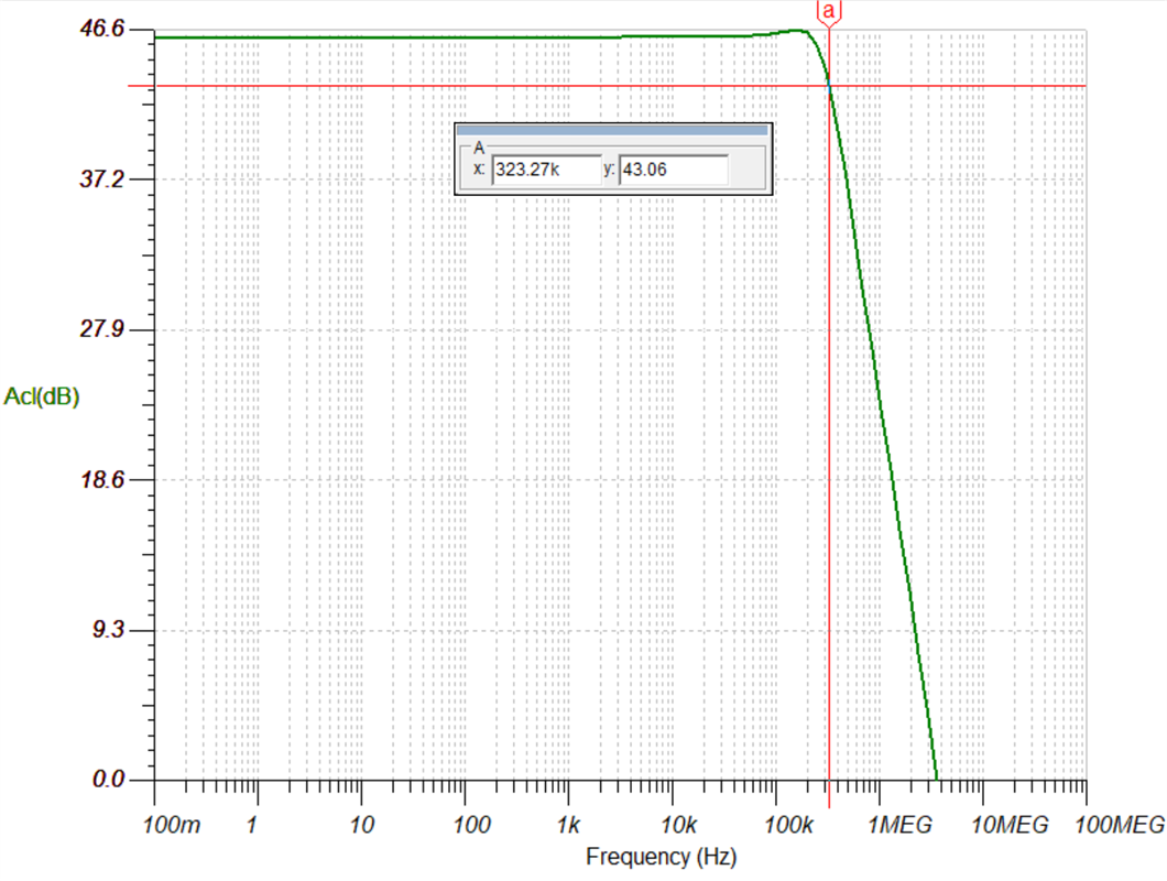
    The gain bandwidth for the JFET circuit is shown below. The inductive nature of the antenna interacts with the gate capacitance of the JFET and causes gain peaking which can lead to instability. In order to reduce/eliminate the peaking I have added in series resistance to the gates. 

    2043.INA849 with JFE Front End With mic source impedance.TSC1385.INA849.TSC

    I hope this information helps in your design. Let me know if I can be of further assistance. 

    Best Regards, 

    Chris Featherstone

  • Thanks for your detailed answer.

    I have sum questions.

       1.I didn't get the same noise graph (I used your simulation in TINA).

       2. The R3 &R7 (30K ohm) in serial to antenna can change the Q factor? (It's not good for me).

       3. The supply is ±9V.

  • Hello Itamar, 

       1.I didn't get the same noise graph (I used your simulation in TINA)

    How did you run the noise simulation? I ran this as input referred noise and changed the axis to log. 

    2. The R3 &R7 (30K ohm) in serial to antenna can change the Q factor? (It's not good for me).

    The Q factor will be changed by either L,R,C which cannot be avoided when connecting to a pre-amp. Any preamp will have an input resistance which you can optimize in your design to fit your requirements. The input resistors can be adjusted to meet your design needs. The JFET will have input capacitance. The inductance of your antenna is very high and will cause instability in the circuit without compensating it. Without the JFETs the noise will be compromised due to the very high source impedance nature of the antenna and the high current noise of the bipolar input stage.  

      3. The supply is ±9V.

    The circuit can be adjusted to 9V operation. R1 ,R11, R2 and R12 can be adjusted to re-bias the JFETs. 

    Best Regards, 

    Chris Featherstone