This thread has been locked.

If you have a related question, please click the "Ask a related question" button in the top right corner. The newly created question will be automatically linked to this question.

OPA2192: Follower and reverse amplifier circuit output deviation

Part Number: OPA2192
Other Parts Discussed in Thread: OPA192

Dear Bu friend,

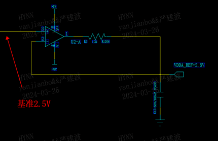
My customer used OPA2192 reference output deviation.The input is 2.5V and the outputs are 2.5V and -2.5V respectively.

Here is the follower circuit.

Here is the reverse amplifier circuit

Test method: Use a six-and-a-half-digit multimeter to collect the reference voltage and op amp output voltage, and power on multiple times to record the values (the following data selects data with large numerical deviations)

Input(V) Follower: +2.5V Reverse:-2.5V
2.49987 2.50048 2.4931
2.49987 2.49983 2.4931
2.49985 2.4998 2.49284

Could you pls give some suggestion? Does it cause by voffest or the drift?

  • Chris,

    1. Connecting capacitors directly to the output of op amps can lead to instability.  I cannot read your schematics, so I cannot simulate your circuit to test for stability.  Nevertheless, I am fairly sure the issue you are seeing is a stability problem.
    2. Placing a resistor between the op amp output and the load capacitor will help stability.  You have to select the correct resistance value.  Determine Optimal Isolation Resistance for Driving Capacitive Load app note describes the selection process (see equation 2).
    3. Placing a resistor inside the feedback (as shown in the top figure) does not act as an isolation resistor.  The resistor needs to be outside the loop.
    4. The image below from the OPA192 data sheet shows the stability vs capacitive load.  Note that the amplifier can tolerate larger capacitors with larger isolation resistors.  

    Best regards, Art Kay