A related question is a question created from another question. When the related question is created, it will be automatically linked to the original question.
If you have a related question, please click the "Ask a related question" button in the top right corner. The newly created question will be automatically linked to this question.
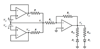
It's a little unfamiliar, hopefully I can convince you to use a more up-to-date op amp. It looks like a inverting summer circuit but instead of sources, they are produced by buffers:
The math for Vx is RL/R * (Va1 + Va2). When RL terminates to ground. A virtual ground in this case.
The left side is a self referencing summer that adds currents to Vx node, so Vx would go infinite gain without a load RL. I can't think of a practical purpose for this circuit.